Panasonic U-8ME1E81 Скачать руководство пользователя страница 1

85464849305004

REFERENCE NO.

SM830205-04

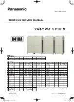
TEST RUN SERVICE MANUAL

2WAY VRF SYSTEM

Model No.

SM830205-01̲2WAY̲SYSTEM.indb   1

2012/04/07   16:35:19

Order No. SBPAC1307003CE

Outdoor Unit

ME1

8HP

U-8ME1E81

10HP

U-10ME1E81

16HP

U-16ME1E81

18HP

U-18ME1E81

20HP

U-20ME1E81

12HP

U-12ME1E81

14HP

U-14ME1E81

Class

Model Name

Class

73

106

140

224

280

E1 High Static Pressure

Ducted

Indoor Unit

Class

15

22

U1

4-Way Cassette

S-22MU1E5

S-22MU1E51

L1

2-Way Cassette

S-22ML1E5

D1

1-Way Cassette

F1

Low Silhouette Ducted

S-22MF1E5

T1

M1

Ceiling

K1

Wall Mounted

S-22MK1E5

R1 Concealed Floor

Standing

S-22MR1E5

P1

Floor Standing

S-22MP1E5

Y1

4-Way Cassette 60×60

S-22MY1E5

F2

Low Silhouette Ducted

S-22MF2E5

Slim Low Static Ducted

S-22MM1E5

S-15MM1E5

28

S-28MU1E5

S-28MU1E51

S-28ML1E5

S-28MF1E5

S-28MD1E5

S-28MK1E5

S-28MR1E5

S-28MP1E5

S-28MY1E5

S-28MF2E5

S-28MM1E5

36

S-36MU1E5

S-36MU1E51

S-36ML1E5

S-36MF1E5

S-36MD1E5

S-36MK1E5

S-36MR1E5

S-36MP1E5

S-36MY1E5

S-36MF2E5

S-36MM1E5

S-36MT1E5

45

S-45MU1E5

S-45MU1E51

S-45ML1E5

S-45MF1E5

S-45MD1E5

S-45MK1E5

S-45MR1E5

S-45MP1E5

S-45MY1E5

S-45MF2E5

S-45MM1E5

S-45MT1E5

56

S-56MU1E5

S-56MU1E51

S-56ML1E5

S-56MF1E5

S-56MD1E5

S-56MK1E5

S-56MR1E5

S-56MP1E5

S-73ME1E5

S-106ME1E5 S-140ME1E5 S-224ME1E5

S-224ME1E5A S-280ME1E5

S-56MY1E5

S-56MF2E5

S-56MM1E5

S-56MT1E5

60

S-60MU1E51

S-60MF2E5

73

S-73MU1E5

S-73MU1E51

S-73ML1E5

S-73MF1E5

S-73MD1E5

S-73MK1E5

S-71MR1E5

S-71MP1E5

S-73MF2E5

S-73MT1E5

90

S-90MU1E51

S-90MF1E5

S-90MF2E5

106

S-106MU1E5

S-106MU1E51

S-106MF1E5

S-106MK1E5

S-106MF2E5

S-106MT1E5

140

S-140MU1E5

S-140MU1E51

S-140MF1E5

S-140MF2E5

S-140MT1E5

160

S-160MU1E5

S-160MU1E51

S-160MF1E5

K2

Wall Mounted

S-22MK2E5

S-28MK2E5

S-36MK2E5

Y2

4-Way Cassette 60×60

S-22MY2E5

S-28MY2E5

S-36MY2E5

S-45MY2E5

S-56MY2E5

S-160MF2E5

SM830205-04_2WAY_VRF_Euro.indb   1

15/01/06   17:34:50

Содержание U-8ME1E81

Страница 1: ...MR1E5 S 28MP1E5 S 28MY1E5 S 28MF2E5 S 28MM1E5 36 S 36MU1E5 S 36MU1E51 S 36ML1E5 S 36MF1E5 S 36MD1E5 S 36MK1E5 S 36MR1E5 S 36MP1E5 S 36MY1E5 S 36MF2E5 S 36MM1E5 S 36MT1E5 45 S 45MU1E5 S 45MU1E51 S 45ML1E5 S 45MF1E5 S 45MD1E5 S 45MK1E5 S 45MR1E5 S 45MP1E5 S 45MY1E5 S 45MF2E5 S 45MM1E5 S 45MT1E5 56 S 56MU1E5 S 56MU1E51 S 56ML1E5 S 56MF1E5 S 56MD1E5 S 56MK1E5 S 56MR1E5 S 56MP1E5 S 73ME1E5 S 106ME1E5 S...

Страница 2: ...n to all warning and caution notices given in this manual WARNING This symbol refers to a hazard or unsafe practice which can result in severe personal injury or death CAUTION This symbol refers to a hazard or unsafe practice which can result in personal injury or product or property damage If Necessary Get Help These instructions are all you need for most installation sites and maintenance condit...

Страница 3: ...will cause the generation of poisonous gas Keep all tubing runs as short as possible Use the flare method for connecting tubing Check carefully for leaks before starting the test run Do not leak refrigerant while piping work for an installation or re installation and while repairing refrigeration parts Handle liquid refrigerant carefully as it may cause frostbite When Transporting Be careful when ...

Страница 4: ...y object into the FAN CASE You may be injured and the unit may be damaged When Servicing Turn the power OFF at the main power box mains wait at least 10 minutes until it is discharged then open the unit to check or repair electrical parts and wiring Keep your fingers and clothing away from any moving parts Clean up the site after you finish remembering to check that no metal scraps or bits of wiri...

Страница 5: ...e of the need for effective use of floor space individual control energy conservation by curtailing heat and carrying power etc Most importantly the multi air conditioner system is able to replenish a large amount of refrigerant compared to conventional individual air conditioners If a single unit of the multi air conditioner system is to be installed in a small room select a suitable model and in...

Страница 6: ...non azeotrope recharging the refrigerant in gas form can lower performance and cause defects in the unit 2 2 Since refrigerant composition changes and performance decreases when gas leaks collect the remaining refrigerant and recharge the required total amount of new refrigerant after fixing the leak 3 Different tools required 3 1 Tool specifications have been changed due to the characteristics of...

Страница 7: ...arm Display 3 2 2 Outdoor Unit Control Panel LED Display 3 4 3 Remote Controller Servicing Functions 3 5 4 2WAY Alarm Codes 3 8 5 Blinking Inspection Display 3 29 6 Inspection and Characteristics of Parts 3 31 7 Test Pin 3 33 8 Symptom Thermostat in OFF continues or cycles OFF ON too frequently 3 34 4 PCB Settings 4 1 1 Outdoor Unit Control PCB 4 2 5 Self Diagnostics Function Table 5 1 1 Self Diag...

Страница 8: ...vii MEMO SM830205 04_2WAY_VRF_Euro indb 8 15 01 06 17 34 51 ...

Страница 9: ...TEM Address Settings 1 2 3 4 5 6 7 8 Contents 1 Address Settings Outdoor Units 1 Test Run 1 2 2 Settings of Indoor Unit Control PCB 1 3 3 Auto Address Setting 1 5 SM830205 04_2WAY_VRF_Euro indb 1 15 01 20 15 15 21 ...

Страница 10: ...uit the automatic address pin CN30 on the outdoor main unit PCB for 1 second or longer then release it Note It is not necessary to remove the socket that is used to short circuit the terminal plugs from the outdoor sub unit PCBs Start indoor and outdoor unit heating operation LED 1 and 2 blink alternately Start indoor and outdoor unit cooling operation LED 1 and 2 blink alternately Are LEDs 1 and ...

Страница 11: ...2 m e t s y S 0 o t t e S N O 2 1 0 3 m e t s y S Examples of the No of outdoor units settings SW6 No of outdoor units Outdoor unit setting SW6 3P DIP switch blue 1 unit factory setting 1 ON 2 units 2 ON 3 units 1 2 ON Address setting of main outdoor unit SW5 Unit No setting Address setting of outdoor unit SW5 3P DIP switch blue Unit No 1 main unit factory setting 2 1 3 Address setting of sub outd...

Страница 12: ...k CN23 When set to short circuit changes to the test run mode The test run mode is automatically cancelled after an hour When short circuit is cancelled the test run mode is cancelled RC socket 3P Blue CN73 Connects to the outdoor unit maintenance remote control and the content of an alarm message will be checked Drive pin 2P Black CN27 When the pulse signal applied after short circuit all indoor ...

Страница 13: ...utdoor main unit control PCB short circuit the automatic address pin CN30 for 1 second or longer then release it Communication for automatic address setting begins To cancel again short circuit the automatic address pin CN30 for 1 second or longer then release it The LED that indicates that automatic address setting is in progress turns OFF and the process is stopped Be sure to perform automatic a...

Страница 14: ...sub unit settings Unit number setting unit No 2 Unit No 2 Sub Unit No 1 Main Outdoor unit system 2 To other system link wiring Indoor unit Inter unit control wiring Remote control communication wiring Make settings as appropriate for the cases listed below Refer to the instructions on the following pages Indoor and outdoor unit power can be turned ON for each system separately Indoor and outdoor u...

Страница 15: ...or units DIP switch SW4 to 1 2 3 1 and set the rotary switch SW3 to 3 5 6 Turn on power to all indoor and outdoor units in the system Short circuit the automatic address pin at the outdoor main unit CN30 for 1 second or longer then release it Communication for automatic address setting begins To cancel again short circuit the automatic address pin CN30 for 1 second or longer then release it The LE...

Страница 16: ...e time Communication for automatic address setting begins the compressors turn ON and automatic address setting in Heating mode begins All indoor units operate To cancel again short circuit the automatic address pin CN30 for 1 second or longer then release it The LED that indicates automatic address setting is in progress turns OFF and the process is stopped Be sure to perform automatic address se...

Страница 17: ... it Be sure to perform this process for one system at a time Automatic address settings cannot be performed for more than one system at the same time Communication for automatic address setting begins the compressors turn ON and automatic address setting in Cooling mode begins All indoor units operate To cancel again short circuit the automatic address pin CN30 for 1 second or longer then release ...

Страница 18: ...e at both sides remains unchanged at shipment Open circuit the refrigerant systems except for 2 locations mentioned above More than 3 short circuit locations of the termination resistors are prohibited remains unchanged at shipment There is no necessary to adjust the termination resistor short circuit remained at shipment because VRF systems for combination of sub outdoor units are not connected t...

Страница 19: ...de Centralized control system No 1 Refrigerant circuit No 2 Refrigerant circuit No n Refrigerant circuit Unit No 1 Main Unit No 2 Sub Unit No 3 Sub Remote control communication wiring Outdoor unit system 1 Indoor unit Outdoor unit system n Inter outdoor unit control wiring Inter outdoor unit control wiring Leave the socket that is used to short circuit the terminal plug CN67 Between conductors Bet...

Страница 20: ...o communication with the indoor units in that system is possible After the power is turned ON and automatic address setting is not in progress 1 or more indoor units are confirmed in that system however the number of indoor units does not match the number that was set Automatic address setting is in progress Alternating Automatic address setting completed At time of automatic address setting the n...

Страница 21: ... is displayed on the remote controller This message disappears when automatic address setting is completed 5 Repeat the same steps to perform automatic address setting for each successive system SETTING Procedure of CZ RTC3 1 Keep pressing the and for 4 or more seconds buttons simultaneously The Maintenance func screen appears on the LCD display 2 Press the or button to see each menu If you wish t...

Страница 22: ...oor unit starts and that air is discharged 5 button again and check the address of each indoor unit in sequence 6 Press and hold the ALL is displayed on the remote controller Next press the The address is displayed for 1 of the indoor units which is connected to Press the Press the button again to return to normal remote controller mode Indoor unit address Number changes to indicate which indoor u...

Страница 23: ...Functions Contents 2 Remote Controller Functions 1 Remote Controller Test Run Settings 2 2 2 Simple Settings Function 2 3 3 Detailed Settings Function 2 7 4 Remote Controller Servicing Functions 2 22 SM830205 04_2WAY_VRF_Euro indb 1 2015 01 23 11 53 20 ...

Страница 24: ...des a timer function that cancels the test run after 60 minutes The operation is possible even if the cassette type ceiling panel has not been installed P09 display does not occur Wired Remote Controller Test Run Settings Procedure of CZ RTC2 CZ RTC3 Procedure of CZ RTC3 Keep pressing the 1 2 and buttons simultaneously for 4 or more seconds The Maintenance func screen appears on the LCD display Pr...

Страница 25: ...a are displayed blinking on the remote controller LCD display Fig 2 1 At this time the indoor unit fan or all indoor unit fans in the case of group control begins operating If group control is in effect press the button and select the address unit No of the indoor unit to set At this time the fan at the indoor unit begins operating If unit No is displayed the same setting will be made for all indo...

Страница 26: ...y pressing the or button Select one of the Set data by pressing the or button Then press the button 5 Select the Unit no by pressing the or button and press the button The Exit simple settings and restart Simple setting end screen appears on the LCD display Select YES and press the button Procedure of CZ RTC3 Fig 2 2 CZ RTC3 START 20 30 THU Maintenance func 1 Outdoor unit error data 2 Service cont...

Страница 27: ...hifts intake temperature 1 C down Shifts intake temperature 2 C down Shifts intake temperature 3 C down Shifts intake temperature 4 C down Shifts intake temperature 5 C down Shifts intake temperature 6 C down Electric heater installation Humidifying when heater thermostat is OFF 0000 0001 0000 0001 No heater Heater installed No setting at time of shipping Yes Permit prohibit Function of EXCT plug ...

Страница 28: ...sign ON time Standard Long life Standard High fouling Standard High fouling 0001 4 Way cassette U1 4 Way cassette 60x60 Y1 Y2 2500 1250 0002 2 Way cassette L1 2500 1250 0003 1 Way cassette D1 2500 1250 0005 Low Silhouette Ducted F1 F2 Slim Low Static Ducted M1 0006 High Static Pressure Ducted E1 0007 Ceiling T1 1500 750 0008 Wall Mounted K1 K2 150 75 0010 Floor Standing P1 150 75 0011 Concealed Fl...

Страница 29: ... the case of group control item code and settings data are displayed blinking on the remote controller LCD display Fig 2 3 At this time the indoor unit fan or all indoor unit fans in the case of group control begins operating If group control is in effect press the button and select the address unit No of the indoor unit to set At this time the fan at the indoor unit begins operating Press the tem...

Страница 30: ...out separate setting Swing Move to position 2 and stay Move to position 3 and stay Move to position 4 and stay Move to position 5 and stay 2 3 4 5 Fig 2 4 NOTE Setting the Flap Separately When setting the CZ RTC2 1 The 4 air outlet flap can be adjusted separately during operation When not adjusted separately all flaps operate in the same manner Procedure Stop the system before performing these ste...

Страница 31: ...ng the or button or keeping it pressed 4 Select the Set data by pressing the or button Select one of the Set data by pressing the or button Then press the button 5 Select the Unit no by pressing the or button and press the button The Exit detailed settings and restart Detailed setting end screen appears on the LCD display Select YES and press the button Maintenance func 1 Outdoor unit error data 2...

Страница 32: ... intake temperature shift 0010 Shifts intake temperature 10 C up 0000 Function disabled 0001 Stops automatically 5 minutes after operation starts 0002 Stops automatically 10 minutes after operation starts 0123 Stops automatically 615 minutes after operation starts 0124 Stops automatically 620 minutes after operation starts Automatic stop time after operation start Can be set in 5 minute units 0125...

Страница 33: ...3 C 7 C 18 C 19 C 29 C 30 C 16 C 17 C 29 C 30 C 18 C 19 C 29 C 30 C 17 C 18 C 26 C 27 C Shifts discharge temperature setting 9 C down Shifts discharge temperature setting 8 C down Normal None Used for OFF reminder Ignore heat exchanger temperature conditions Filter input differential pressure switch input Alarm input for trouble input about air cleaner or similar device Humidifier input Operates l...

Страница 34: ...inked with fan ON when indoor unit fan is operating Fan output switching 0001 Fan mode operation output 0000 No delayed start 0001 1 second delayed start 0002 2 seconds delayed start 0058 Except Indoor unit Type U1 F2 T1 E1 Indoor unit Type U1 F2 T1 E1 58 seconds delayed start 0059 59 seconds delayed start Drain pump delayed start time 0060 60 seconds delayed start 1 minute delayed start 2 minutes...

Страница 35: ...r ON time ON time per 60 seconds 0060 Continuously ON 0000 Function disabled Repeat timer switching 0001 Function enabled 0000 Function disabled Timer function change prohibit 0001 Function enabled Smudging control 0000 No smudging control 91 90 Flap 1 Motor No 4 Motor No 1 Motor No 2 Motor No 3 Flap 3 Flap 2 Flap 4 92 93 Electrical component box Flap position 1 2 3 4 5 Setting the Flap Separately...

Страница 36: ...controller setting data Contents optional parts name 0000 3 0003 0003 6 0006 0003 0003 Standard setting at time of shipping Air blocking material for 3 way air discharge Air blocking material when a discharge duct is connected Air blocking material for 2 way air discharge Table 1 Table of DC Fan Motor Tap Settings 4 Way Cassette type Setting No Remote controller setting data Purpose of use names o...

Страница 37: ...0 30 THU 4 Select the Code no by pressing the or button Change the Code no to 5D by pressing the or button or keeping it pressed Detailed settings Unit no Code no Set data 1 0 0 0 1 1 Sel Next 20 30 THU 5D 5 Select the Set data by pressing the or button Select one of the Set data in Table for DC Fan Motor Tap Setting Table 1 Table 3 by pressing the or button Then press the button 6 Detailed settin...

Страница 38: ...1 2P red on the indoor unit con trol PCB If the setting No is 3 then connect the jumper connector to the connector pin TP3 2P yellow on the indoor unit control PCB 1 Way Cassette Procedure Be sure to turn OFF the main power source before performing the steps below Open the electrical component box cover then check the indoor unit control PCB Fig 2 8 Connect the jumper connector 2P yellow which was...

Страница 39: ...ed Short circuit the applicable short circuit pin in accordance with the selected short circuit pin connected 150 Pa TP3 2P yellow short circuit 140 Pa TP1 2P red short circuit Use the short circuit connector 2P yellow supplied Table of selection of connected short circuit pins External static pressure at the time of rated airflow volume Short circuit pin Unusable 150 Pa 140 Pa TP6 2P white TP3 2P...

Страница 40: ...e button for 4 or more seconds will be displayed on the remote controller s LCD display 2 Press the button to commence the test run Test Run will be displayed on the remote controller s LCD display 3 Select the fan mode and set it to H by pressing the button Auto airflow volume control operations and external static pressure setting check operations will not be performed unless H has been selected...

Страница 41: ...ext 20 30 THU B0 4 Select the Set data by pressing the or button Select one of the Set data among 0001 0015 according to the desired external static pressure setting by pressing the or button Then press the button See the table below For details refer to the section 8 EXTERNAL STATIC PRESSURE SETTING of the Installation Instructions When setting to auto airflow volume control Select the setting da...

Страница 42: ...CD display and press the button The Test run screen appears on the LCD display Test run setting mode screen appears on the LCD display Change the display from OFF to ON by pressing the or button Then press the button The Maintenance func screen appears on the LCD display TEST START 20 30 THU START 20 30 THU 9 Press the 11 Press the The LCD display will be returned to the initial screen button butt...

Страница 43: ...ty Press and hold the buttons and simultaneously for 4 seconds or longer If group control is in effect press the button and select the address unit No of the indoor unit to set At this time the fan at the indoor unit begins operating Use the temperature setting buttons to select item code 1C Make a choice from 6 level of numeric display 0000 to 0005 Press the timer time buttons to select the desir...

Страница 44: ...ger Press the button When settings are made from a remote controller the indoor unit where that remote controller is connected stops Automatic address Automatic address setting based on command from the wired remote controller Press and hold the and the timer operation buttons for 4 seconds or longer Automatic reset Address change Change of indoor unit address Entire system stops Press and hold th...

Страница 45: ...ption Menu selection Reset operation Unit status Test run Operation with forced thermostat ON 4 Test run Press the button Sensor temperature display Temperature display from each sensor 5 Sensor info Servicing check display Alarm history display 6 Service check Simple settings Filter lifetime operating mode priority central control address and other settings 7 Simple settings Press the button Rest...

Страница 46: ...n the LCD display 2 Press the or button to see each menu If you wish to see the next screen instantly press the or button Select 4 Test run on the LCD display and press the button Change the display from OFF to ON by pressing the or button Then press the button Maintenance func 1 Outdoor unit error data 2 Service contact 3 RC setting mode 4 Test run Sel Page Confirm Sel Page Confirm 20 30 THU Main...

Страница 47: ...itor For the relationships between the sensor addresses and sensor types refer to the table of temperature sensors and addresses below If group control is in effect press the button to select the unit to monitor Press the temperature setting buttons to select the item code to change Press the button to return to normal remote controller display The temperature display appears as for units that are...

Страница 48: ...y sensor information of the unit Refer the information by pressing the or button Maintenance func 1 Outdoor unit error data 2 Service contact 3 RC setting mode 4 Test run Sel Page Confirm 20 30 THU Maintenance func 5 Sensor info 6 Servicing check 8 Detailed settings Sel Page Confirm 20 30 THU 7 Simple settings Sensor info Unit no Code no Data Sel Next 20 30 THU 01 02 00 0028 0026 0026 1 1 Sensor i...

Страница 49: ...ual operating frequency MOV pulse 4 MOV4 Low pressure sensor temp Suction temp SCT Detected oil temp 1 OIL1 Detected oil temp 2 OIL2 Detected oil temp 3 OIL3 0A 0B 0C 0D 0E 0F 10 11 12 13 14 15 16 17 18 19 1A 1B 1C 1D 1E 1F 20 21 22 23 24 2A 2B 2C 2D 2E 2F 30 31 32 33 34 35 36 37 38 39 3A 3B 3C 3D 3E 3F 40 41 42 43 44 4A 4B 4C 4D 4E 4F 50 51 52 53 54 55 56 57 58 59 5A 5B 5C 5D 5E 5F 60 61 62 63 64...

Страница 50: ...2 28 MEMO SM830205 04_2WAY_VRF_Euro indb 28 2015 01 23 11 53 29 ...

Страница 51: ... 2 Outdoor Unit Control Panel LED Display 3 4 3 Remote Controller Servicing Functions 3 5 4 2WAY Alarm Codes 3 8 5 Blinking Inspection Display 3 29 6 Inspection and Characteristics of Parts 3 31 7 Test Pin 3 33 8 Symptom Thermostat in OFF continues or cycles OFF ON too frequently 3 34 SM830205 04_2WAY_VRF_Euro indb 1 15 01 20 15 29 42 ...

Страница 52: ...mber set Improper setting Improper setting Improper setting Indoor unit Number of connected indoor units is less than the number set Number of connected indoor units is more than the number set No indoor unit is connected during auto address setting Main outdoor unit is detecting error signal from sub outdoor unit Duplicated outdoor unit address Improper wiring between main outdoor unit and sub un...

Страница 53: ...d state of indoor units are inoperative Indoor unit communication error of group control wiring P02 P04 P03 P05 P20 P18 P17 P29 P31 P22 P16 Operating and timer lamps blinking alternately Timer and heat ready lamp blinking alternately Operating and heat ready lamp blinking alternately 1 Contents of Remote Controller Switch Alarm Display 2WAY SYSTEM Trouble Diagnosis alarm indication In some cases m...

Страница 54: ...y After the power is turned ON and auto matic address setting is not in progress the number of detected indoor units connected to that system matches the number that was set and regular communications are occurring Automatic address setting is in progress At time of automatic address setting the number of indoor units did not match the number that was set Alarm display LED 1 blinks M times then LE...

Страница 55: ...rvice monitor 00XX sensor temperature See figure at right Press the temperature setting and buttons to change the item code to the sensor address of the sensor you wish to monitor For the relationship between the sensor address and sensor type refer to the ensor emperature elationship able on next page If group control is in effect press the button to change to the unit you wish to monitor Press t...

Страница 56: ...y sensor information of the unit Refer the information by pressing the or button Maintenance func 1 Outdoor unit error data 2 Service contact 3 RC setting mode 4 Test run Sel Page Confirm 20 30 THU Maintenance func 5 Sensor info 6 Servicing check 8 Detailed settings Sel Page Confirm 20 30 THU 7 Simple settings Sensor info Unit no Code no Data Sel Next 20 30 THU 01 02 00 0028 0026 0026 1 1 Sensor i...

Страница 57: ...sor address Sensor type Sensor address Sensor type Indoor unit Remote controller temp Room temp controlled Discharge air temp BL Discharge air temp setting Indoor unit intake temp TA Indoor unit heat exchanger temp E1 E1 Indoor unit MOV pulse MOV Indoor unit heat exchanger temp E3 E3 Outdoor unit Unit No 1 Unit No 2 Unit No 3 Unit No 1 Unit No 2 Unit No 3 Discharge temp 1 DISCH1 Discharge temp 2 D...

Страница 58: ...ube SCG Low pressure sensor trouble Gas temperature sensor trouble at outdoor heat exchanger 2 EXG2 Liquid temperature sensor trouble at outdoor heat exchanger 2 EXL2 Outdoor unit non volatile memory EEPROM trouble 3 17 3 18 Compressor 1 current trouble 3 17 3 18 3 19 Constant speed compressor 2 overcurrent alarm Constant speed compressor 2 lock current alarm Compressor 1 CT sensor disconnected or...

Страница 59: ...ble High pressure switch activated Reverse phase or missing phase detected Compressor 1 INV overcurrent alarm Compressor 2 discharge temperature trouble Compressor 3 discharge temperature trouble Fan motor trouble Inverter compressor missing phase or lock alarm Compressor thermal protector is activated trip only and no alarm 3 23 P14 3 26 O2 sensor differential alarm Only when optional O2 sensor s...

Страница 60: ...rogress Then start automatic address setting again Example Notes E12 Automatic address setting start is prohibited Automatic address setting was started when automatic address setting was in progress at Automatic address setting is in progress at another outdoor unit This alarm is not displayed on the remote controller Therefore check the blinking on the outdoor Wait for automatic address setting ...

Страница 61: ...utdoor unit 3 The power is OFF at all indoor units in the system Check 2 Check whether serial connector 1 CN76 is disconnected at the outdoor unit 3 Check the power at the indoor units Correction Example Notes E20 No indoor units at automatic address setting When automatic address setting was performed no indoor units were recognized 1 The inter unit control wiring from the outdoor unit to the ind...

Страница 62: ...etting Recovery from this alarm occurs automatically when the set outdoor unit quantity matches the number of outdoor units detected on the outdoor unit main sub control wiring E29 Alarm Alarm code Alarm meaning Alarm conditions Probable cause 1 After initial communications were completed the outdoor unit main sub control wiring was cut 2 After initial communications were completed the RC connecto...

Страница 63: ...erature at times fluctuates suddenly and wildly In some cases the precise temperature may not be known even when monitoring software is used Check Wiggle the sensor and check whether the trouble continues Check whether the connector is partially disconnected from the PCB An F04 alarm will not result if the connector is completely disconnected circuit is open If the cause is still uncertain check t...

Страница 64: ...a high discharge temperature then the compressor may stop for no apparent reason The purpose of this alarm is to facilitate identification of the problem in this case F06 F23 Alarm Alarm code F06 F23 Alarm meaning Gas temperature sensor trouble at outdoor heat exchanger 1 Gas temperature sensor trouble at outdoor heat exchanger 2 Alarm conditions 1 A D step is 10 steps or less short circuit 2 A D ...

Страница 65: ...ss short circuit 2 A D step is 1014 steps or more open circuit Probable cause 1 Sensor malfunction including connector 2 PCB malfunction Check 1 Measure the sensor resistance Check that the sensor is operating normally 2 Use a remote controller monitor or PC monitor to check the temperature that is recognized by the microcomputer Correction Example Notes F14 Alarm Alarm code F14 Alarm meaning SCG ...

Страница 66: ...ooling and indoor unit heating Sudden rise in pressure at start may sometimes occur 4 Check for clogging of the refrigerant circuit 6 Outdoor unit PCB failure 5 Check for refrigerant over charging A normal PCB is needed to determine whether the problem is a PCB failure or a pressure sensor malfunction If an abnormality was found at the check items for a high pressure sensor malfunction first try re...

Страница 67: ...den voltage decrease 2 Operating under extremely high pressure status over loaded operation Check open closed status of the service valve of the outdoor unit 3 Check power source and voltage H01 Alarm Alarm code Alarm meaning Alarm conditions Probable cause Check Correction Example Notes H01 Compressor 1 Current trouble Compressor 1 INV primary current detected overcurrent higher than the values o...

Страница 68: ... or PCB continuity trouble occur However this may not be true in the case of a missing phase caused by magnet SW trouble Check There is the possibility of a magnet SW failure Therefore check the phase voltage at a location that is as close to the compressor as possible 4 Low power voltage Trouble In most cases this occurs when another constant speed compressor including compressors in other units ...

Страница 69: ...ing H03 Compressor 1 CT sensor disconnected or short circuit H23 Compressor 3 CT sensor disconnected or short circuit Alarm conditions Compressor 1 Compressor 2 3 When the compressor 1 INV is stopped the primary current detected over 18A Current values at compressor 2 and 3 are less than 2 0 A when 2 seconds or more had passed after the compressors began operation and output When the frequency of ...

Страница 70: ...ter and measure the resistance between sensor No 1 and No 3 Connect a gauge to the low pressure outlet and check for changes in the value displayed by the monitoring software and for large deviation of the gauge pressure Resistance of less than 95k Check the open closed status of the service valve 3 Check for clogging of the refrigerant circuit When clogging in the refrigerant circuit occurs refri...

Страница 71: ...essor 3 Alarm conditions This alarm occurs when a connector connection pins 1 and 2 for compressor 1 pins 4 and 5 for compressor 2 and pins 7 and 8 for compressor 3 is open Probable cause Disconnected connector Check Check that the connector is securely connected Correction 1 Connect the connector 2 Correct the connection at connector pins 4 and 5 Example Notes SM830205 04_2WAY_VRF_Euro indb 21 15...

Страница 72: ...C If there is a short circuit there is an HIC malfunction Correction Example Notes If an HIC failure is found replace the PCB Turn OFF the power and check the continuity of HIC and HIC on the HIC PCB L04 Alarm Alarm code Alarm meaning Alarm conditions that unit 5 times or more within 3 minutes Probable cause Check Correction Example Notes L04 Outdoor system address duplication Communication by int...

Страница 73: ...as connected by mistake 1 Check the refrigerant type at the connected unit The outdoor unit maintenance remote controller is required in order to set the refrigerant type in the outdoor unit EEPROM L18 Alarm Alarm code Alarm meaning Alarm conditions Probable cause 2 The 4 way valve circuit is locked malfunctioning Check 2 If the connector is normal check the 4 way valve wiring and the PCB circuit ...

Страница 74: ...it stops there is the sound of refrigerant flowing into an outdoor unit that was stopped for a long time When an outdoor unit starts after being stopped for a long time the start is accompanied by much vibration Check Check Check the following points limited to the stopped outdoor units while the other outdoor units are operating Refrigerant leak on the expansion valves MOV1 MOV2 MOV4 Refrigerant ...

Страница 75: ...ed it will remain in that state until the pressure goes below 3 15 MPa Probable cause 1 3 2 4 5 6 7 8 9 High pressure switch failure or wiring connection failure Difference of characteristics of high pressure sensor Failure to open the service valve of the outdoor unit Clogging of the outdoor heat exchanger during cooling Air short circuit occurs during cooling Failure of the outdoor fan during co...

Страница 76: ...to resolve this trouble by limiting the maximum frequency Secondary 28A 36A 6 horsepower compressors 10 horsepower compressors L1 Power terminal board Prim ary current L2 L3 N Inverter compressor HIC PCB U V W Secondary current P14 Alarm Alarm code Alarm meaning Alarm conditions Probable cause Check and Correction Example Notes P14 O2 sensor operation 1 1 1 System configuration Is an O2 sensor bei...

Страница 77: ...f there is a short circuit there is an HIC malfunction Correction 1 If there is a fan HIC failure or circuit failure replace the PCB 2 If the fan motor is locked replace the fan motor Example Notes If the fan does not start the below corrections may be effective Turn OFF the power and check the continuity of and on the fan circuit PCB P20 Alarm Alarm code P20 Alarm meaning Alarm conditions Probabl...

Страница 78: ...art or when inverter compressor lock occurs there is a missing phase in the inverter compressor wiring or a DCCT failure occurs This can be judged to be starting trouble which is not caused by HIC Check Check the power wiring and connector wiring Correction DCCT failure replace PCB or compressor failure Example Notes Use a tester to measure the voltage between the DCCT output terminal on the rear ...

Страница 79: ...eck the alarm history then refer to the corresponding items Correction Follow the instructions in the corresponding items to correct the trouble Recovery After repairing the malfunctioning locations reset the power for the system all outdoor units Caution Automatic backup mode will not be canceled until the power is reset Notes Automatic backup mode is not engaged in cases of alarms other than tho...

Страница 80: ... conditions of magnet SW operation are poor difficult to open Õ When a magnet SW is used in a DC circuit it may be difficult for the SW to open at times In an AC circuit the magnet SW should open instantaneously as long as the current is within the allowable range However this kind of trouble can occur if excessive current flows and may prevent the SW from opening 2 CT circuit failure or PCB failu...

Страница 81: ...roximately 46Ω If the results are 0Ω or replace the coil When the voltage is normal measure the resistance between each pair of pins on the electronic control valve connector The connector is normal if all results pin 5 pin 1 pin 5 pin 2 pin 5 pin 3 pin 5 pin 4 are approximately 46Ω If the results are 0Ω or replace the coil MOV2 Measure the voltage between plug pin 5 and pins 1 through 4 at the CN...

Страница 82: ... 1 716 1 667 4 Coil Resistance of Outdoor Unit Fan Motor 5 Coil Resistance of Compressor Motor 6 Characteristics of Thermistor Resistor kΩ Resistor kΩ Ambient air temperature thermistor TO Suction temperature thermistor SCT Temperature C Temperature C Refrigerant gas outlet of dual tube thermistor SCG Heat exchanger liquid temperature thermistor EXL Heat exchanger gas temperature thermistor EXG 40...

Страница 83: ... then turn the power back ON Output is performed in the sequence shown in the table below for 0 5 seconds each Operation Operation Output Relay RY12 4 way valve 20s Relay RY8 Save valve SAVE Output Relay RY2 6 7 8 9 Relay RY1 1 2 3 4 5 Relay RY4 Bypass valve BPV Relay RY6 Oil recovery valve ORVR Relay RY3 Crankcase 2 CH2 Crankcase 1 CH1 Crankcase 3 CH3 Relay RY11 Refrigerant balance valve RBV Rela...

Страница 84: ...C socket on outdoor unit main control PC board and check alarm messages See operational status 2 2 Yes No 2 2 Discharge temperature is over 80 C in stop mode and does not decrease Connect outdoor maintenance remote controller to RC socket on outdoor unit main control PC board and check alarm messages Replace discharge temperature sensor 2 3 Yes No 2 3 Demand value always stays low The value is low...

Страница 85: ...4 1 1 2 3 4 5 6 7 8 2WAY SYSTEM PCB Settings Contents 4 PCB Settings 1 Outdoor Unit Control PCB 4 2 SM830205 04_2WAY_VRF_Euro indb 1 15 01 20 15 31 35 ...

Страница 86: ...PS CN49 Comp discharge 3 temp DISCH3 CN59 Comp discharge 1 temp DISCH1 CN55 Comp discharge 2 temp DISCH2 CN56 Gas temp sensor at heat exchanger 1 2 EXG1 2 CN61 Liquid temp sensor at heat exchanger 1 2 EXL1 2 CN60 High pressure sensor HPS CN46 CT2 CT3 FORCED STOP DEMAND Suction temp SCT CN65 CTL2 CTL1 Oil detection sensor OIL1 2 3 CN54 HIC2 HIC1 HIC3 SW6 SW1 LED4 SW7 EEPROM memory IC IC14 LED3 Alar...

Страница 87: ...dress 10s digit and 20s digit SW2 If 10 systems or more are set the setting is made by a combination of this DIP switch and SW1 If 10 19 systems are set set switch 1 10s digit to ON If 20 29 systems are set set switch 2 20s digit to ON and set switch 1 10s digit to OFF If 30 systems are set set both switch 1 10s digit and switch 2 20s digit to ON For details concerning SW1 and SW2 refer to Table 1...

Страница 88: ...black This pin is used to test the PCB at the factory When the power is turned ON after this pin has been short circuited all output signals will be output in sequence Sequential output does not occur if this pin is short circuited when the power is already ON Releasing this pin returns the unit to normal control 3WAY SYSTEM PCB Settings 1 Outdoor Unit Control PCB 2P plug black Stop pin Short circ...

Страница 89: ... 3 4 5 6 7 8 9 0 OFF OFF OFF OFF OFF OFF OFF OFF OFF OFF ON ON ON ON ON ON ON ON ON ON ON ON 1P 10s digit 2P 20s digit 1 2 3 OFF OFF OFF OFF ON ON ON OFF OFF OFF OFF OFF OFF OFF ON ON ON OFF OFF ON ON ON ON ON OFF OFF OFF OFF OFF OFF ON OFF ON ON OFF OFF OFF OFF OFF OFF ON ON ON ON ON ON ON ON 1 2 3 9 0 1 9 0 1 9 0 1 9 0 1 9 0 1 9 0 1 3 4 2 1 2 3 9 10 11 19 20 21 29 30 31 39 40 41 49 50 51 59 60 6...

Страница 90: ...4 6 MEMO SM830205 04_2WAY_VRF_Euro indb 6 15 01 20 15 31 37 ...

Страница 91: ...5 1 1 2 3 4 5 6 7 8 2WAY SYSTEM Self Diagnostics Function Table Contents 5 Self Diagnostics Function Table 1 Self Diagnostics Function Table 5 2 SM830205 04_2WAY_VRF_Euro indb 1 14 12 25 16 58 35 ...

Страница 92: ...connected correctly Check that the indoor unit power is ON An alarm appears on the wired remote controller sometime from several seconds to several minutes after automatic address setting is started LED 1 and 2 on the outdoor unit control PCB indicate that automatic address setting is in progress the LEDs blink alternately for several minutes after automatic address setting is started the compress...

Страница 93: ...ller of an indoor unit where the indoor unit address is not set is inadvertently operated Communications with the outdoor unit are not possible The remote controller is not connected correctly trouble with sending of the signal from the remote controller to the indoor unit Check that the inter unit control wiring is connected correctly Check that there are no open circuits short circuits terminal ...

Страница 94: ...sensor trouble Compressor 3 discharge temperature sensor trouble Gas temperature sensor trouble at outdoor heat exchanger 2 Liquid temperature sensor trouble at outdoor heat exchanger 2 F31 Outdoor unit non volatile memory EEPROM trouble Compressor 1 CT sensor disconnected or short circuit Low pressure trouble Compressor 1 oil detection sensor connection trouble Constant speed compressor 2 overcur...

Страница 95: ...6 1 1 2 3 4 5 6 7 8 2WAY SYSTEM Service Checker Contents 6 Service Checker 1 Outdoor Unit Maintenance Remote Controller 6 2 SM830205 04_2WAY_VRF_Euro indb 1 2015 01 23 11 53 52 ...

Страница 96: ...2 Remote controller Assy Operation manual included in package Outdoor unit Outdoor unit control PCB Inter unit control wiring CZ RTC2 Indoor unit Indoor unit Remote controller Remote controller The special service checker wiring is required in order to connect the outdoor unit maintenance remote controller to the outdoor unit PCB Ordinary remote controllers or other controllers are still required ...

Страница 97: ... the outdoor unit PCB The connection diagram is shown below Fig 6 1 Fig 6 2 All units start stop Fig 6 1 Operation The ON OFF operation button can be used to start and stop all indoor units The LED illuminates if any indoor unit is operating The LED blinks if an alarm occurs at any of the operating indoor units Cooling heating change Fig 6 1 Operation Cooling and heating mode changes are only avai...

Страница 98: ...3 oil level Compressor 3 operation count Alarm history 1 most recent Alarm history 2 Alarm history 3 Alarm history 4 Alarm history 5 Alarm history 6 Alarm history 7 Alarm history 8 oldest Firmware version Program version Alarm code display Quantity 7 segment display 7 segment display 7 segment display 1 3 7 segment display 7 segment display 0 99999999 hours 0 99999999 hours 0 99999999 hours 0 Empt...

Страница 99: ...X Outdoor unit system address 1 30 YY Outdoor unit address 1 4 The locations where and are displayed as shown in Fig 6 3 Fig 6 4 Fig 6 5 No of connected indoor units 4 units connected Unit Nos 1 2 3 4 connected Sample display Fig 6 4 Fig 6 5 1 Outdoor Unit Maintenance Remote Controller SM830205 04_2WAY_VRF_Euro indb 5 2015 01 23 11 53 54 ...

Страница 100: ...ve passed press the FLAP button With the outdoor unit maintenance remote controller when connected to the outdoor unit the unit remote controller check functions will not operate An 8 digit display is used for display of the compressor total operating time in 1 hour units When the first 4 digits are displayed the top dot of the colon is illuminated Figure A When the last 4 digits are displayed the...

Страница 101: ... outdoor unit data 0A 24 are for unit No 1 2A 44 are for unit No 2 4A 64 are for unit No 3 NOTE 1 2 3 4 1 Outdoor Unit Maintenance Remote Controller Remarks Description DN C C C C C C C C C C C C C C C C C C C C Indoor unit intake temp TA Indoor unit heat exchanger temp E1 E1 Indoor unit heat exchanger temp E3 E3 Indoor unit Discharge air temp BL Discharge air temp setting Indoor unit MOV pulse MO...

Страница 102: ...play shows the outdoor unit address Press the UNIT button and select the outdoor unit for which to monitor the alarm history Press the temperature setting and buttons and select the item code for the alarm history The selected outdoor unit address the item code and the alarm history alarm data are displayed The outdoor unit address is displayed as R C XX YY R C XX Outdoor unit system address YY Ou...

Страница 103: ...igits Fig A and the last 3 digits Fig B When the first 3 digits are displayed the bottom dot of the colon is illuminated A and B are displayed alternately Example shows display of 000 001 A Display of first 3 digits B Display of last 3 digits 1 Outdoor Unit Maintenance Remote Controller Description Parameter DN Snowfall sensor usage 000 Sensor input not present Control is performed 001 Sensor inpu...

Страница 104: ...e shows 000 410 R410A C Display of first 3 digits D Display of last 3 digits 3 1 5 During this mode is displayed blinking The display shows the set outdoor unit address System XX YY System XX System address YY Address at outdoor unit sub bus item code number DN value in the table below and the setting data 6 digits The setting data is displayed in 6 digits The display changes between the first 3 d...

Страница 105: ...201502 SM830205 04_2WAY_VRF_Euro indb 1 15 02 13 17 04 58 ...

Отзывы: