


47
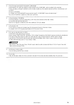
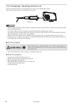
2-5 Connecting Laser Marker
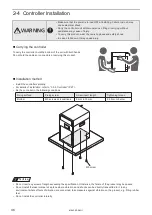
WARNING
• Be sure to turn the power off before you conduct wiring or connection. Failure
to do so may cause electrical shock.
• Be sure to connect the head and controller of the laser marker which have the
same model number. Otherwise there is a risk of exposure to laser radiation
or failure.
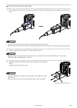
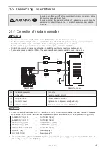
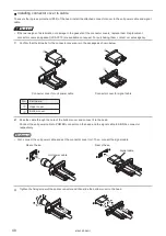
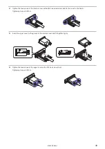
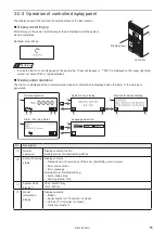
2-5-1 Connection of head and controller
ワㄐㄕㄊㄆ
• It is recommended to connect the head and controller that have the identical serial numbers.
• For the connection of this product, use the dedicated cables attached to the product or the specified optional cables.
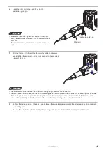
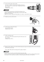
• Insert the cable all the way in a straight line. Tilting and inserting the cable may cause a failure.
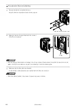
• Be careful not to apply excess force to the cable or not to nip the cable at the installation.
• Verify the minimum bend radius of each cable and install them without excess forces being applied.
• To ensure the ingress protection (IP64) of the head, install the attached connector covers to the cables.
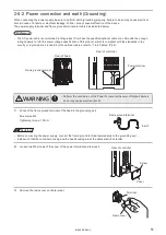
q
w
r
e
e
Rear of controller
Rear of head
No.
Cable and connector
Connector
q
Signal cable
Signal connector: SIGNAL
w
Unit power cable
Power connector: POWER
e
Connector cover
Signal cable / Unit power cable (head side)
r
I/O terminal block
I/O terminal block connector: TERMINAL
ンㄆㄇㄆㄓㄆㄏㄆ
• Connect the following terminals of the I/O terminal block. If any of them is not connected, the laser radiation is disabled.
When shipped, some of these terminals are connected with a shot bar. Refer to “4-5-1 Factory default wiring” (P.101).
LASER STOP IN (X10)
―
OUT COM. 1 (X12)
LASER STOP IN (X11)
―
OUT COM. 1 (X12)
INTERLOCK 1(+) (X16)
―
INTERLOCK 1(-) (X17)
INTERLOCK 2(+) (X18)
―
INTERLOCK 2(-) (X19)
REMOTE INTERLOCK (X20)
―
OUT COM. 1 (X12)
IN COM. 1 (X2)
―
Power supply *1
OUT COM. 1 (Y2)
―
Power supply *1
*1 : Connect IN COM. 1 (X2) and OUT COM. 1 (Y2) respectively to the power supply for input and output. Refer to “4-5-2
Connecting common terminals” (P.102).
ME-LPRF-SM-11
Содержание LP-RF Series
Страница 17: ...1 Product Overview ME LPRF SM 11...
Страница 34: ...2 Laser Marker Installation ME LPRF SM 11...
Страница 57: ...3 Operation Method ME LPRF SM 11...
Страница 81: ...4 External Control Using I O ME LPRF SM 11...
Страница 126: ...5 External Control by Communication Commands ME LPRF SM 11...
Страница 135: ...6 Link Control with External Devices ME LPRF SM 11...
Страница 160: ...7 Maintenance ME LPRF SM 11...
Страница 186: ...Troubleshooting ME LPRF SM 11...
Страница 214: ...Index ME LPRF SM 11...
Страница 216: ...216 USB 32 55 W Warning 205 ME LPRF SM 11...
Страница 217: ......


