29
1-2 Product Configuration
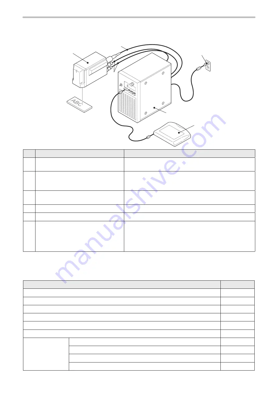
This product is a laser marker which is designed to mark and process the object by radiating a laser beam to the target.
The laser marker LP-M series consists mainly of the following units.
q
w
y
t
r
e
No. Name
Description
q
Head
It is the unit that radiates the laser beam. The optical components
and the scanner are loaded inside.
w
Controller
It is the unit that stores the setting data and controls the operation.
The main power supply, laser oscillator and connection interface
with external devices are loaded.
e
Unit power cable (Attached accessory)
Signal cable (Attached accessory)
Cables to connect the head and controller.
r
Fiber cable
Cable to deliver the laser beam from controller to head.
t
AC power cable (Attached accessory)
Cable to supply AC power to the controller.
y
Touch panel console (Optional item)
or
Commercially available monitor and mouse
(Not included in this product.)
Connect the touch panel console or monitor and mouse to the
laser marker to set the marking data and other parameters. This
display can be used also as a monitor during the operation.
It is also possible to configure the marking data with PC by
installing the attached software “Laser Marker Utility”.
Optional items
The following optional items (sold separately) are available for this product.
To purchase them and for the detailed information, please contact our sales office.
Optional items
Model
Touch panel console
LP-ADP40
Air filter (for replacement)
LP-AFT50X5
Protection glass of laser emission port (for replacement)
LP-ACV70
Unit power cable (for replacement)
LP-ACP30-5
Signal cable (for replacement)
LP-ACS30-5
3D setting software NAVI LINK-3D
LP-APC20
AC power cable (for
replacement)
Rating 125V, PSE and CSA/UL standards compatible (North America, Japan)
LP-ACA10
Rating 250V, PSE standards compatible (Japan)
LP-ACA11
Rating 250V, VDE standards compatible (Europe), for LP-Mxxx-LS1 type
LP-ACA12-LS1
Rating 250V, VDE standards compatible (Europe)
LP-ACA12
ME-LPM-SSM-10
Содержание LP-M Series
Страница 16: ...16 MEMO ME LPM SSM 10...
Страница 27: ...27 Chapter 1 Specification ME LPM SSM 10...
Страница 37: ...37 Chapter 2 Preparation ME LPM SSM 10...
Страница 69: ...Chapter 3 Connection for External Control ME LPM SSM 10...
Страница 128: ...Chapter 4 Maintenance ME LPM SSM 10...
Страница 148: ...Troubleshooting ME LPM SSM 10...
Страница 169: ...Index ME LPM SSM 10...
Страница 172: ...172 MEMO No 9000 0066 34V ME LPM SSM 10...
Страница 173: ...No 9000 0066 34V...

