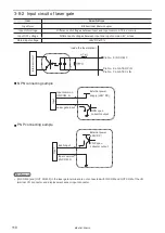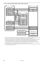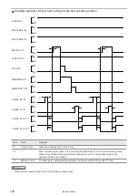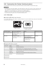
116
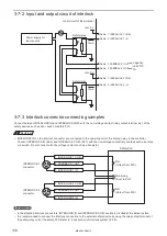
3-7-2 Input and output circuit of interlock
Pin No. 1. INTERLOCK 1 COM.
15mA
+24V DC
+24V DC
Pin No. 3. INTERLOCK 1 IN
Pin No. 1. INTERLOCK 2 COM.
Pin No. 3. INTERLOCK 2 IN
Pin No. 2. FEEDBACK 1 OUT
Pin No. 2. FEEDBACK 2 OUT
15mA
Inner circuit of laser marker
Safety relay
Safety relay
Capacity:
+24V DC
1A
Power supply for
laser source
3-7-3 Interlock connector connecting samples
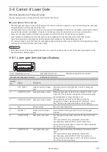
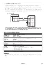
Connect between INTERLOCK IN and INTERLOCK COM. with the non-voltage contact (relay output terminal etc.) of the
safety devices such as door, switch or safety PLC.
ワㄐㄕㄊㄆ
• INTERLOCK IN on the interlock connector are connected to the operating coil of the internal relay in the controller.
Connect INTERLOCK IN (No.3) and INTERLOCK COM. (No.1) with the non-voltage contact (dry contact) such as a relay
or a switch. Do not connect with the voltage contact such as a transistor.
1. INTERLOCK 1 COM.
INTERLOCK 1
connector
2. FEEDBACK 1 OUT
3. INTERLOCK 1 IN
1
2
3
1. INTERLOCK 2 COM.
INTERLOCK 2
connector
2. FEEDBACK 2 OUT
3. INTERLOCK 2 IN
1
2
3
Safety PLC
N.O.
(Output from PLC)
Monitoring
(Input to PLC)
N.O.
(Output from PLC)
ンㄆㄇㄆㄓㄆㄏㄆ
• In the attached interlock connectors, INTERLOCK IN and INTERLOCK COM. are short-circuited at the delivery state.
• It is recommended to connect the interlock connectors to the external safety device by using the relay output terminal of
the safety relay unit or the safety PLC. Refer to “Construction of interlock system” (P.26).
ME-LPM-SSM-10
Содержание LP-M Series
Страница 16: ...16 MEMO ME LPM SSM 10...
Страница 27: ...27 Chapter 1 Specification ME LPM SSM 10...
Страница 37: ...37 Chapter 2 Preparation ME LPM SSM 10...
Страница 69: ...Chapter 3 Connection for External Control ME LPM SSM 10...
Страница 128: ...Chapter 4 Maintenance ME LPM SSM 10...
Страница 148: ...Troubleshooting ME LPM SSM 10...
Страница 169: ...Index ME LPM SSM 10...
Страница 172: ...172 MEMO No 9000 0066 34V ME LPM SSM 10...
Страница 173: ...No 9000 0066 34V...


