background image

72

Scan Tool User Guide

Special Test Screen Examples

15: Special Tests (Actuator Tests)

Special Test Screen Examples

There are two basic types of special test screens: 
instructional and bi-directional control.

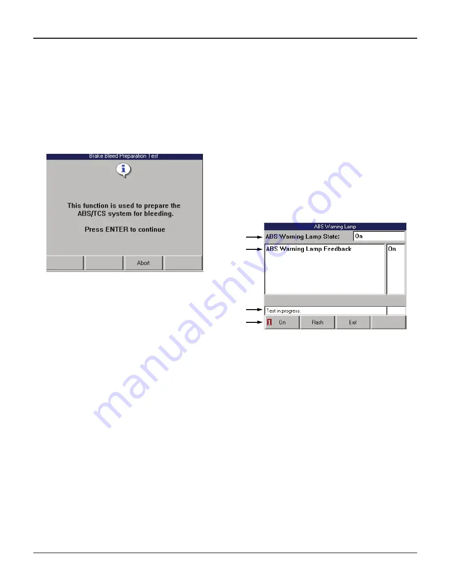
Instructional Screen Example

Instructional screens contain step-by-step instruc-
tions for performing a special test. You simply follow 
the instructions provided on each screen.

Figure 15.2: Instructional Screen Example

Bi-Directional Control Screen 
Examples

The bi-directional control screens vary in appear-
ance, but they all allow you to manually control the 
vehicle’s relays, solenoids, lamps, and other compo-
nents. 

Basic Single Component Control Screen

The following screen is the basic manual control 
screen for a single component. You press the Start 
function key to begin and then use the On and Off 
function keys to control the component.

Figure 15.3: Single Component Control Screen Example

Item 1

This area displays the command you have issued 
through the scan tool (On, Off).

Item 2

This area displays the state of the component being read 
by the ECU. The bottom of this area may also contain 
special test instructions.

Item 3

The status line displays the current status of the test. 

Item 4

The function keys let you manually control the compo-
nent as necessary. Compare what is commanded by the 
scan tool to the state of the component being read by the 
ECU to the actual physical state of the component.

1

2

3

4

Содержание Genisys EVO

Страница 1: ...Genisys EVO User Guide...

Страница 2: ...erwise without the prior written permission of SPX Microsoft and Microsoft Windows are trademarks or registered trademarks of Microsoft Corporation in the United States and or other countries Windows...

Страница 3: ...Tool 13 Connect the Hardware Module optional 13 Adjust Default Settings 14 Scan Diagnostics Applications 15 Overview 15 Test Startup and Vehicle Connection 16 Step 1 Enter the Vehicle Information 16...

Страница 4: ...Print 46 Zoom 46 Sort 47 English Metric Units 48 Show Hide LED Bar 48 Show Hide Analog 49 Conflict 50 Remembered Settings 50 DTC Triggered Recording 50 Custom Datastream 51 Integrated Diagnostics Sca...

Страница 5: ...nstructional Screen Example 72 Bi Directional Control Screen Examples 72 Playback 75 Playback Instructions 75 Copy Files To From USB Drive 76 System Setup 77 Basic Procedure 77 Contrast Adjust 77 Prin...

Страница 6: ...e around moving components or belts during testing Moving components and belts can catch loose clothing body parts or test equipment and cause serious damage or personal injury Automotive batteries co...

Страница 7: ...below For details refer to User Inter face Selection on page 80 Figure 1 2 Application Manager Screen Examples Scan Diagnostics this option leads to the vehicle diagnostic software applications Domest...

Страница 8: ...k access to the Global OBD II application if held down while turning the scan tool on 4 Direction Keys Up Down Left and Right select an option or scroll through a screen of data or text 5 EXIT Key exi...

Страница 9: ...View 1 On Off Button turns the scan tool on and off When using external power the scan tool stays on until you turn it off When using internal battery power the scan tool turns off automatically after...

Страница 10: ...iews 1 Memory Card Slot with Cover holds the System Memory Card DO NOT REMOVE MEMORY CARD UNLESS PERFORMING UPDATES TO CARD 2 PC Card Slot holds an interface card for devices such as a modem Ethernet...

Страница 11: ...ns the scan tool s operating software and applications IMPORTANT DO NOT REMOVE THE MEMORY CARD UNLESS PERFORMING UPDATES TO THE CARD PC Card optional Figure 1 12 Wireless PC Card The PC card is an opt...

Страница 12: ...art Cable for On Board Diagnostic II OBD II vehicles Figure 1 15 OBD II Smart Cable System Smart 25 Pin Cable 3305 73 System Smart 25 pin cable for OBD II vehicles Figure 1 16 System Smart 25 Pin Cabl...

Страница 13: ...the menu and are grey screen contrast must be properly adjusted In addition free software updates for the tool are available periodically on the Internet at www geni sysotc com For complete instructio...

Страница 14: ...er screen Figure 1 20 on page 7 the Repair Information screen appears as shown below Figure 1 23 Repair Information Screen Classic User Interface This screen contains options for using the following s...

Страница 15: ...ter tests and special component and vehicle system tests This is the Scope Multimeter software application integrated with the InfoTech application Scope data displays on the top half of the screen an...

Страница 16: ...d print header functions on or off Revision Levels view software version numbers Wireless Network Settings Classic only set up IP addresses for wireless communication between the scan tool and a PC or...

Страница 17: ...tion menu You can also print the User Guide For help using the file select Help Adobe Reader Help from the main menu or press F1 on the keyboard NOTE To view the User Guides the Adobe Acrobat Reader s...

Страница 18: ...12 Scan Tool User Guide Software Descriptions 1 General Information Notes...

Страница 19: ...an Tool see Figure 2 1 The battery is fully charged in 3 hours IMPORTANT For maximum battery life do not leave the charger connected more than 12 hours Connect the Hardware Module optional If using th...

Страница 20: ...ide power to the scan tool press the On Off button to turn the scan tool on and wait for the Appli cation Manager screen to appear 2 Use the Down Direction key to select System Setup and then press th...

Страница 21: ...nual provided with the GM SPS Reprogramming application To perform scan diagnostic tests you select an application from the Scan Diagnostics screen enter vehicle information into the scan tool connect...

Страница 22: ...the ENTER key If you select Global OBD II the Required Cables illustration appears go to step 8 on page 18 If you select Domestic Asian ABS Air Bag Latin America European or Heavy Duty Standard a seri...

Страница 23: ...p 8 on page page 18 NOTE On the Vehicle Information screens you can press the Demo function key to display demonstration data in the software The Demo function stays on until you press the function ke...

Страница 24: ...rough a stan dardized J 1962 data link connection DLC Non OBD II A vehicle not equipped with an OBD II system generally uses the DB25 Power cable 3305 72 which supplies communication through a DLC con...

Страница 25: ...key NOTE Make sure the scan tool and vehicle are communicating 7 Do one of the following If the Performing Quick Tests message and then the Global OBD II Quick Test results screen appears Figure 3 13...

Страница 26: ...e 51 Integrated Diagnostics Scan Gas to view exhaust gas readings CO CO2 HC O2 NOX AFR along with the sensor and switch datastream readings For details refer to Inte grated Diagnostics Scan Gas on pag...

Страница 27: ...ure 4 2 Quick DTC Scan Report Screen NOTE For more information about DTCs refer to Diagnostic Trouble Codes on page 27 3 Notice the following about the Quick DTC Scan Report screen You use the Up and...

Страница 28: ...on about DTCs refer to Diagnostic Trouble Codes on page 27 2 Select the line for a DTC 3 If the status bar indicates related information is available press the ENTER key This displays a Code Options s...

Страница 29: ...t Report screen Figure 5 2 System Analysis Test Report Screen 3 Notice the following about the System Analysis Test Report screen You use the Up and Down Direction keys to scroll through the data and...

Страница 30: ...press the Print function key to print the test results Refer to Printing on page 83 You can use the Summary function key to return to the System Analysis Test Report screen Pressing the EXIT key exits...

Страница 31: ...or details refer to Datastream on page 39 6 When finished use the EXIT key to return to previous screens Freeze Frame Data Mode 2 When you select highlight the line for a freeze frame item see Figure...

Страница 32: ...test 3 If the status bar indicates viewing of component details is available press the ENTER key Figure 5 10 Component Tests Screen 4 Optionally use the Refresh function key to display new data for th...

Страница 33: ...iggered Record function For vehicles with datastream access if a diagnostic fault occurs while you are testing a vehicle the software auto matically alerts you with a screen message and creates a reco...

Страница 34: ...s you do a wiggle test to check for intermittent breaks in circuitry 3 Do one of the following If the Read Codes menu screen appears Figure 6 4 go to step 4 If the DTC Information screen appears Figur...

Страница 35: ...C Information screen has a Pathfinder function key This function key lets you access the Pathfinder Troubleshooting function from within the scan diagnostic application For details refer to 10 Pathfin...

Страница 36: ...during the last ignition cycle and is current If engine starts is 2 or more the code is present as an intermittent code but is not current If no codes are found a number shows how many engine starts h...

Страница 37: ...view a list of any codes that were read For details refer to Review Codes on page 37 Self Diagnostics Ford Mazda The Self Diagnostic function lets you manually acti vate system tests that check for D...

Страница 38: ...try This section includes the following procedures Output State below Idle Air Adjust on page 33 Wiggle Test on page 33 Output State The Output State test does a KOEO self test see page 31 and then le...

Страница 39: ...st function lets you check for intermit tent breaks in connections and for open or short circuits by manually wiggling vehicle wires 1 Follow the steps in Read and Display Codes on page 27 to display...

Страница 40: ...nction key to complete the test 10 Use the EXIT key to return to previous screens NOTE When finished do a KOEO test see Self Diag nostics Ford Mazda on page 31 Failure Records GM Saturn Isuzu The Fail...

Страница 41: ...ing of codes as one procedure and viewing of codes as a separate procedure review NOTE These steps only read the DTCs You have to use the Review Codes procedure page 37 to view codes after reading the...

Страница 42: ...rinting information refer to Print on page 46 3 Press the ENTER key This displays the DTC Retrieval Procedure screen Figure 6 25 DTC Retrieval Procedure Screen 4 View the retrieval procedure and optio...

Страница 43: ...d press the ENTER key Figure 6 29 Review Codes Select Screen 3 If the Review Codes Select screen appears select one of the following options and then press the ENTER key to display the codes Otherwise...

Страница 44: ...g If the Diagnostic Trouble Codes menu screen appears Figure 6 32 go to step 3 If an instruction screen appears Figure 6 33 go to step 4 Figure 6 32 Diagnostic Trouble Codes Menu Screen 3 Select Clear...

Страница 45: ...irst time you test a vehicle the top line displays in Graph format and the remaining lines display in Digital format See Remembered Settings on page 50 The screen s data updates as the software reads...

Страница 46: ...the data from English to Metric or vice versa See page 48 Show Hide LED Bar displays a row of LED read ings directly above the status line and function keys The LED readings are for frequently monitor...

Страница 47: ...able USB Drive If there is a portable USB Drive inserted in the scan tool s USB port the Record function saves data files that occur after pressing the Record key to the USB drive You can then view pl...

Страница 48: ...appear when you press the key 3 Repeat steps 1 and 2 for each line to change About Digital Display When a line is displayed as Digital its reading is a word or a number as shown for all the lines in F...

Страница 49: ...e graph For some sensors an average reading appears between the minimum and maximum measurements not shown The average reading can be useful in spotting data trends NOTE You can use the Left and Right...

Страница 50: ...lines remain locked for the selected vehicle until you unlock them even if you exit the software 4 To unlock a locked line select the locked line and then press the ENTER key see steps 1 and 2 To Top...

Страница 51: ...for each frame 3 Use the Left or Right Direction keys to move backward or forward through the data frame by frame 4 When finished press the EXIT key to return to the normal screen display and to resum...

Страница 52: ...ress the OK function key Zoom The Zoom function on the Datastream screen s More menu lets you magnify the view of each data line on the Datastream screen NOTE This function applies to digital graph an...

Страница 53: ...ort by Locked function one or more lines must be locked 1 With the Datastream screen displayed press the MORE function key 2 Use the Down Direction key to select the Sort function 3 Press the ENTER ke...

Страница 54: ...re that will appear after you select the option 3 Press the ENTER key This displays the data in the selected units of measure Show Hide LED Bar The Show Hide LED Bar function on the Datastream screen...

Страница 55: ...he More menu lets you temporarily hide the gauges or display them again NOTE To originally display analog gauges or to entirely turn them off refer to Graph Analog LED Digital on page 42 To hide or sh...

Страница 56: ...the PCMs reported the data If there is a large difference between the read ings for an item suspect a broken wire or PCM fault 6 After viewing the items use the EXIT key to return to previous screens...

Страница 57: ...atastream Selection Screen before selections 3 Select the data items to include in the Datastream display as follows a Use the Up and Down Direction key to select an item to include in the display b P...

Страница 58: ...52 Scan Tool User Guide NOTES...

Страница 59: ...the instructions on the screen and then press the OK function key This zeros the gas module and then displays the live data readings Figure 9 3 Figure 9 3 Gas and Data Display 5 Do the following to sh...

Страница 60: ...ou counted in step a 10 to 12 seconds is average d Press the OK function key to display the shifted data readings Figure 9 6 Datastream with Data Shifted and Lined Up 6 Notice the three snaps of the t...

Страница 61: ...Troubleshooting Screen 3 Select the item to view and press the ENTER key 4 Refer to the remaining sections in this chapter for specific instructions for each option on the Pathfinder Troubleshooting s...

Страница 62: ...the ENTER key Figure 10 3 Fast Fix Select Category Screen 3 Several screens appear for selecting a category symptom and component From each screen select an item and then press the ENTER key Do this u...

Страница 63: ...the description and print it if necessary Refer to Print on page 46 4 Use the EXIT key to return to previous screens Tune Up Specifications The Tune Up Specifications option lets you view a descriptio...

Страница 64: ...gure 10 8 Code Information Screen 3 Select a code and press the ENTER key Figure 10 9 Options Screen 4 Select an option and press the ENTER key Circuit Description displays a summary of the circuit op...

Страница 65: ...print it Refer to Print on page 46 7 When finished use the EXIT key to return to previous screens Data Sensor Information The Data Sensor Information function lets you view vehicle specific sensor and...

Страница 66: ...n 4 View the description and optionally print it Refer to Print on page 46 5 Use the EXIT key to return to previous screens PCM Connector Pin Information B O B The PCM Connector Pin Information B O B...

Страница 67: ...to previous screens Component Location The Component Location option lets you view a description of the computer and connector locations for a vehicle 1 Follow the steps in Basic Procedure on page 55...

Страница 68: ...al Bleed Procedure screen or the Pressure Bleed Procedure screen Figure 10 21 Brake Bleed Procedure Example Screens 4 View the procedure and optionally print it Refer to Print on page 46 5 Use the EXI...

Страница 69: ...gnostic Menu Screen and Vehicle Info Screen 3 Select the item to view and press the ENTER key 4 Refer to the following sections Specifications next column TSB References on page 64 System Type on page...

Страница 70: ...vehicle description 1 Follow the steps in Basic Procedure on page 63 to display the Vehicle Info screen see Figure 11 1 2 Select System Type and press the ENTER key to display the System Information...

Страница 71: ...2 Select Prom ID and press the ENTER key Figure 12 2 Prom ID Screen 3 View the information 4 Use the EXIT key to return to previous screens Controller ID The Controller ID function displays identifica...

Страница 72: ...66 Scan Tool User Guide NOTES...

Страница 73: ...t data is unavailable or unreliable Vehicle service manuals refer to this mode as 10 K Ohm State or Special State 1 Follow the instructions in Test Startup and Vehicle Connection on page 16 to display...

Страница 74: ...68 Scan Tool User Guide NOTES...

Страница 75: ...the Diagnostic Trouble Codes menu screen appears Figure 14 3 Diagnostic Trouble Codes Menu Screen 5 Do one of the following If the SIR warning lamp is off the procedure is complete Use the EXIT key to...

Страница 76: ...70 Scan Tool User Guide NOTES...

Страница 77: ...rovided on the scan tool screens WARNING During active testing bi direc tional component activation is automatically inhib ited when required to allow components adequate time to cool down Do not bypa...

Страница 78: ...compo nents Basic Single Component Control Screen The following screen is the basic manual control screen for a single component You press the Start function key to begin and then use the On and Off f...

Страница 79: ...anded by the scan tool to the state of the component being read by the ECU to the actual physical state of the component Item 5 The More menu contains basic Datastream functions For details refer to D...

Страница 80: ...ions Item 4 The status line displays the current status of the test Item 5 The Start function key starts the test Activate Deactivate Screen The following screen is an example of a manual control scre...

Страница 81: ...old recordings automatically delete as you make new recordings To prevent a recording from being automatically deleted highlight the recording and press the Save function key This places a disk icon...

Страница 82: ...elect From USB to copy files from the USB drive to the scan tool NOTE The tool holds up to 25 files If neces sary delete files from the tool to make room for copying files from the USB drive Select To...

Страница 83: ...Defaults on page 79 Revision Levels on page 79 Wireless Network Settings on page 79 Technical Support on page 80 User Interface Selection on page 80 Color Scheme Selection on page 80 Function Key Ass...

Страница 84: ...reports that you print from the scan tool NOTE You can turn the Print Header function on and off with the Unit Defaults settings Refer to Unit Defaults on page 79 1 Follow the steps in Basic Procedure...

Страница 85: ...ey to select an option for the box 6 For Date and Time repeat steps 4 and 5 to enter the entire date or time 7 Use the Left Direction key to go to the far left column 8 Repeat steps 3 through 7 until...

Страница 86: ...off and back on Color Scheme Selection The Color Scheme Selection function lets you set the color of the background and text that appears on the scan tool screens 1 Follow the steps in Basic Procedur...

Страница 87: ...p screen see Figure 17 1 2 Select Language and press the ENTER key Figure 17 13 Language Selection Screen 3 Use the Up and Down Directions keys to select the language 4 Press the Select function key 5...

Страница 88: ...82 Scan Tool User Guide NOTES...

Страница 89: ...inting IMPORTANT The tool infrared port must remain pointed at the printer infrared port until the entire print operation is complete USB Inkjet Printer You can print text and graphics from the scan t...

Страница 90: ...84 Scan Tool User Guide NOTES...

Страница 91: ...include the following information company name contact name telephone number description of the problem proof of purchase for warranty repairs preferred method of payment for non warranty repairs You...

Страница 92: ...2008 SPX Corporation All rights reserved 11 11 08 Part Number 551252...

Отзывы: