Scan Tool User Guide
19
Test Startup and Vehicle Connection
3: Scan Diagnostics Applications
4
Connect the cable’s DLC connector to the vehicle’s
DLC.
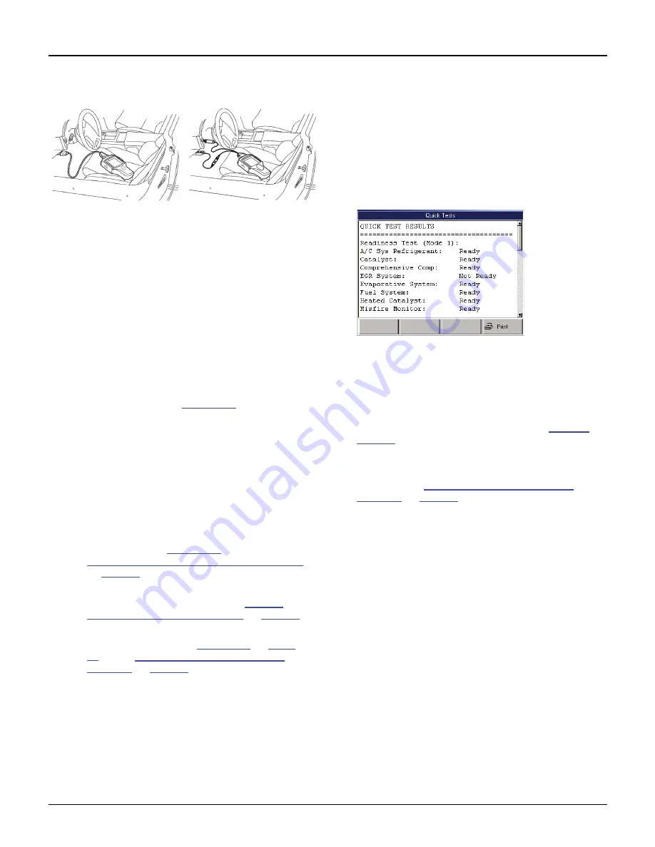
Figure 3.12: Cable Connection to Vehicle DLC: OBD II Smart
Cable or System Smart 25-pin cable (shown on left) and DB25
Power Cable
NOTE: For OBD II vehicles
, the DLC is usually
located under the vehicle dash as shown above.
For non-OBD II vehicles
or for OEM testing, the
DLC may be located elsewhere. Some cable adapt-
ers may have multiple connectors or may have test
leads that connect to the vehicle DLC.
For Heavy
Duty vehicles,
the connector may be in or under
the dash, behind the driver-side kick-panel, or
behind the left side of the driver’s seat. Do not use
any connectors located under the hood.
5
For the DB25 Power cable, connect the cables’s
power plug into the vehicle’s cigarette lighter
receptacle, as shown in
Figure 3.12
(on the right).
NOTE:
Battery Adapter (212638) can be used to
connect the power plug to the vehicle’s battery.
6
With the Required Cables illustration still displayed on
the scan tool screen, press the
ENTER
key.
NOTE:
Make sure the scan tool and vehicle are
communicating.
7
Do one of the following:
•
If the “Performing Quick Tests” message and
then the Global OBD II Quick Test results
screen appears (
Figure 3.13
), continue with
Step 3: View the OBD II Quick Test Results
on
page 19
.
•
If a list of controllers appears (Heavy Duty),
select a controller and then go to
Step 4:
Select the Diagnostic Function
on
page 20
.
•
If either a Message screen or a Diagnostic
Menu screen appears (
Figure 3.14
on
page
20
), go to
Step 4: Select the Diagnostic
Function
on
page 20
.
Step 3: View the OBD II Quick Test
Results
After you connect the cable and press the ENTER
key on the scan tool, use the following steps if the
Quick Test results screen appears.
NOTE:
The Quick Tests provide a quick link to the
vehicle’s PCM for viewing OBD II emissions readiness
tests and readiness test drive cycle information.
Figure 3.13: Quick Test Results Screen
1
Use the
Up
and
Down Direction
keys to scroll
through the test results.
2
Optionally, select the line for a readiness monitor and
press the function key to see drive cycle information.
3
Optionally, print the test results. Refer to
Printing
on
page 83
.
4
After viewing the Quick Test results, press the
ENTER
key.
5
Continue with
Step 4: Select the Diagnostic
Function
on
page 20
.
Содержание Genisys EVO
Страница 1: ...Genisys EVO User Guide...
Страница 18: ...12 Scan Tool User Guide Software Descriptions 1 General Information Notes...
Страница 58: ...52 Scan Tool User Guide NOTES...
Страница 72: ...66 Scan Tool User Guide NOTES...
Страница 74: ...68 Scan Tool User Guide NOTES...
Страница 76: ...70 Scan Tool User Guide NOTES...
Страница 88: ...82 Scan Tool User Guide NOTES...
Страница 90: ...84 Scan Tool User Guide NOTES...
Страница 92: ...2008 SPX Corporation All rights reserved 11 11 08 Part Number 551252...


