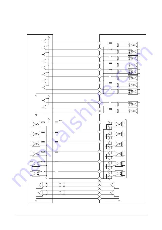
Connection
19
▐
Connecting to a current source output circuit
The fi gure below shows a connection example of the built-in controller type driver. In the case of the pulse input type
with RS-485 communication interface and the pulse input type, the pin No.1, No.2, No.13, and No.14 are only available
to the pulse input. Refer to p.20 for connection example.
IN4 (ZHOME)
IN3 (M2)
IN2 (M1)
IN1 (M0)
IN0 (START)
OUT0 (HOME-END)
OUT1 (IN-POS)
OUT2(PLS-RDY)
OUT3 (READY)
OUT4 (MOVE)
OUT5 (ALM-B)
OUT-COM
IN5(FREE)
IN6 (STOP)
IN7 (ALM-RST)
IN-COM [0-7]
IN8 (FW-JOG)
IN9 (RV-JOG)
IN-COM [8-9]
ASG-
ASG+
BSG-
BSG+
GND
4.7 kΩ
2.2 kΩ
4.7 kΩ
2.2 kΩ
4.7 kΩ
2.2 kΩ
4.7 kΩ
2.2 kΩ
4.7 kΩ
2.2 kΩ
4.7 kΩ
2.2 kΩ
4.7 kΩ
2.2 kΩ
4.7 kΩ
2.2 kΩ
Driver
Controller
0 V
0 V
0 V
24 VDC
12 to 24 VDC
R0
R0
R0
R0
R0
R0
0 V
4.7 kΩ
2.2 kΩ
4.7 kΩ
2.2 kΩ
24 VDC
0 V
26C31 or equivalent
Output saturated
voltage 3 V max.
1
13
2
14
3
15
4
16
5
6
18
17
7
19
8
20
9
21
10
11
23
12
24
22
Twisted pair cable
10 mA or less
* ( ): Initial value


