


Preparation
▌
10
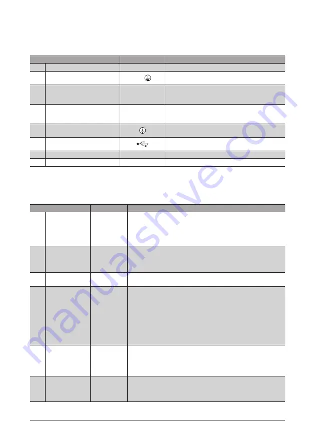
Connector, terminal
Names, indication, and functions for connectors and terminals are common to all drivers.
The RS-485 communication connectors (CN6 and CN7) are not provided in the pulse input type drivers.
Name
Display
Description
3
Encoder connector
CN3
Connects the encoder.
4
Motor connector
CN2,
Connects the motor. (A grounding wire of the motor is
also included.)
6
Electromagnetic brake terminals
(CN1)
MB1, MB2
Connects the lead wires from the electromagnetic brake.
MB1: Electromagnetic brake− (Black)
MB2: Electromagnetic brake+ (White)
7
Power supply input terminals (CN1)
+, −
Connects the power supply.
+: +24 VDC/48 VDC power supply input
−: Power supply ground
8
Protective Earth Terminal (CN1)
Used for grounding via a grounding cable of AWG18 to 16
(0.75 to 1.25 mm
2
).
12
USB communication connector
Connects the PC in which the support software
MEXE02
has been installed. (USB2.0 mini-B port)
13
Input/output signals connector
CN4
Connects the input/output signals.
14
RS-485 communication connector
CN6, CN7
Connects the RS-485 communication cable.
LED, switch
Names, indication, and functions for LEDs and switches vary depending on the driver type. Check in the table below.
Built-in controller type, Pulse input type with RS-485 communication interface
Name
Display
Description
1
POWER/ALARM LED
(Green/Red)
POWER/ALARM
This LED is lit in green while the power is input.
If an alarm (protective function) generates, the LED will blink in red.
If an information generates, the LED will blink in red and green
simultaneously. (Red and green colors may overlap and it may be visible to
orange.)
2
C-DAT/C-ERR LED
(Green/Red)
C-DAT/C-ERR
This LED will blink or illuminate in green when the driver is communicating
with the master station properly via RS-485 communication.
This LED will illuminate in red when a RS-485 communication error occurs
with the master station.
5
HOME PRESET
switch
HOME PRESET
This switch is used to set the starting position (home position) when
performing positioning operation.
9
Function setting
switch
SW1
Use this switch when controlling the system via RS-485 communication.
No.1: Using this switch and the address number setting switch (ID), set the
address number of RS-485 communication.
Factory setting: OFF
No.2: Set the protocol of RS-485 communication.
Factory setting Built-in controller type: OFF
Pulse input type with RS-485 communication interface: ON
No.3, No.4: Sets the termination resistor (120 Ω) of RS-485 communication.
Factory setting: No.3 and No.4: Both OFF
10
Address number
setting switch
ID
Use this switch when controlling the system via RS-485 communication.
Use this switch and SW1-No.1 of the function setting switch, to set the
address number of RS-485 communication.
Factory setting Built-in controller type: 0
Pulse input type with RS-485 communication interface: 1
11
Transmission rate
setting switch
BAUD
Use this switch when controlling the system via RS-485 communication.
Set the transmission rate of RS-485 communication.
Factory setting Built-in controller type: 7
Pulse input type with RS-485 communication interface: 4


