Operation OEM6 Cards and Enclosures
Chapter 4
OEM6 Family Installation and Operation User Manual Rev 12
72
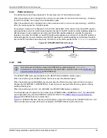
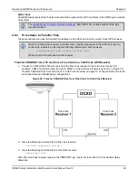
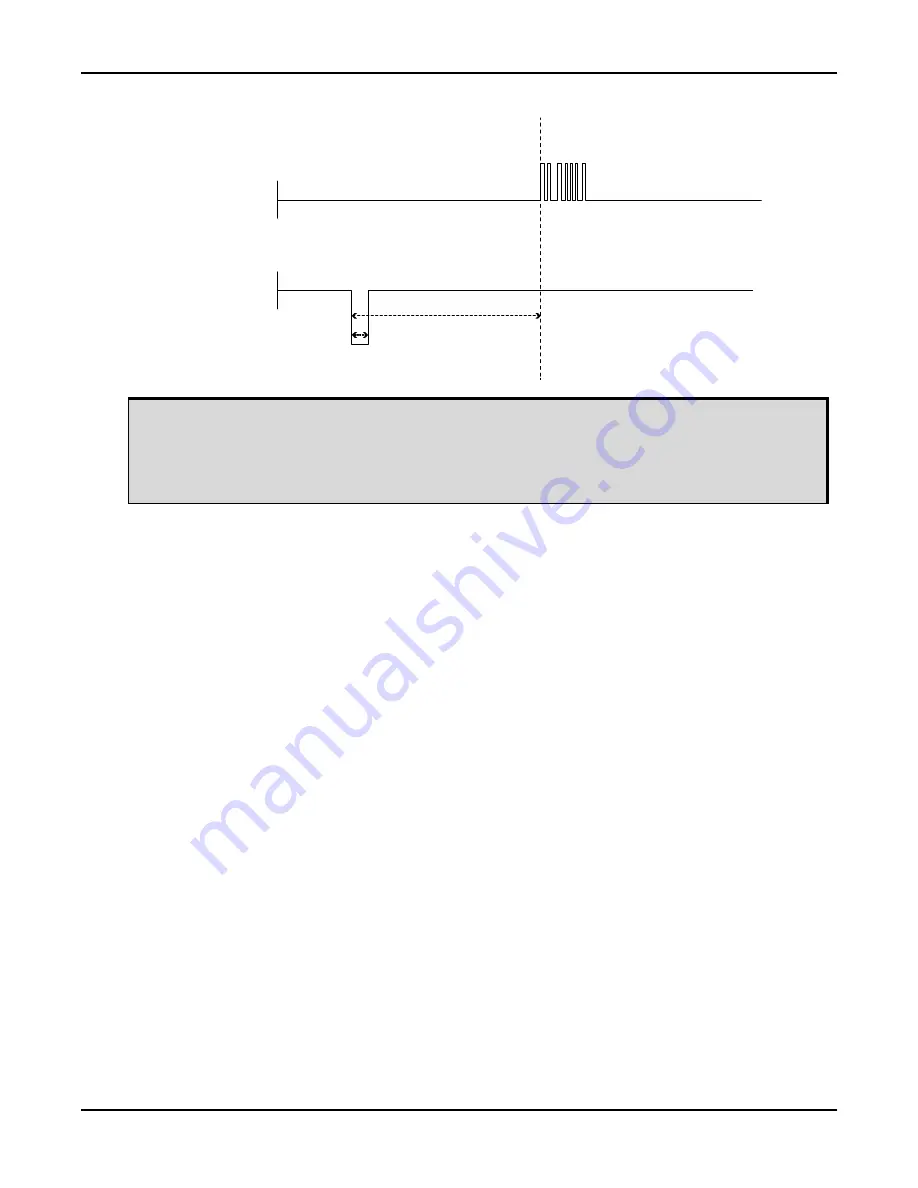
Figure 33: 1 PPS Alignment
The examples shown in
Figure 30, Transfer COARSE Time from Fine Clock to Cold Clock
Figure 31, Transfer FINE Time from Fine Clock to Cold Clock Receiver
page 70 and
Figure 32, Transfer FINE Time from Fine Clock to Warm Clock Receiver
page 71 are for the transfer of time. If a position is needed, the receiver must be tracking
satellites and must have a valid almanac.
Fine Clock
Receiver
connected to COM
Input on Warm
Clock Receiver
1PPS on Fine
Clock Receiver
connected to MK1|
on Warm Clock
Receiver
RS-232
TTL
10 ms
1PPS IN
(1 ms)
TIMESYNC log transmit
time is dependent on
baud rate
The next
TIMESYNC log
is triggered by
the next PPS


