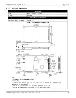
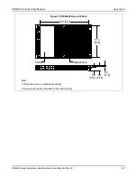

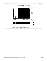


OEM628 Technical Specifications
Appendix D
OEM6 Family Installation and Operation User Manual Rev 12
160
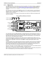
Alternately, use modular jacks with built-in Ethernet magnetics. In that case, run 100
Ω
differential pairs over
unbroken reference planes directly to the jack. Ensure the integrated magnetics in the jack meet the
specifications in the table below. Ensure that the jack is no more than 15 cm (6 inches) from the OEM6
connector. Shorter runs are better.
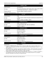
Ethernet cable type (Cat5/Cat5e/Cat6) does not affect the OEM628 emissions profile with a properly laid out
PCB. The following table gives recommended Ethernet transformer characteristics.
An example of a modular jack with integrated Ethernet magnetics is provided in
on page 159. The part and circuit shown there would be suitable for the OEM628 as
well. It is worth noting, however, that environmentally-sealed versions of the jack with integrated magnetics
may not be readily available.
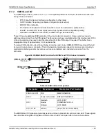
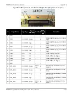
Table 35: Ethernet Transformer Characteristics
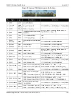
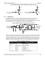
Table 36: Bill of Materials (critical components)
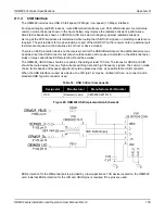
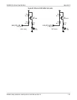
The OEM628 Ethernet LED control lines must be buffered. The buffer structure in the figure below shows a
sample LED drive circuit. Do not use the Ethernet bias 3.3 V (P1502, pins 3 and 6) to drive the LEDs. The
Ethernet bias should only be routed to the Ethernet magnetics.
Parameter
Value
Test Condition
Turns ratio
1 CT : 1 CT
Open-CCT inductance (minimum)
350 uH
100 mV, 100 kHz, 8 mA
Leakage inductance (maximum)
0.4 uH
1 MHz (minimum)
Inter-winding capacitance (minimum)
12 pF
DC resistance (maximum)
0.9
Ω
Insertion loss (maximum)
1.0 dB
0 MHz – 65 MHz
HIPOT (minimum)
1500 Vrms
Designator
Manufacturer
Manufacturer Part Number
FFB100, FB101, FB102 TDK
MMZ1005B800C
U100
Halo
TG110-E050N5RL
U101, U102
Semtech
Bourns
OnSemi
LC03-6.TBT
CDNBS08-PLC03-6
LC03-6R2G
C105, C106, C107
AVX
1206GC102KAT1A