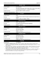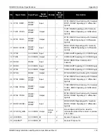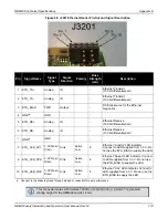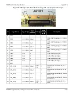
OEM638 Technical Specifications
Appendix E
OEM6 Family Installation and Operation User Manual Rev 12
182
E.1.4
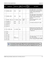
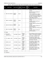
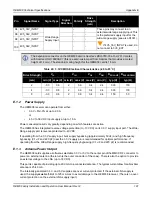
Logic-Level I/O
The OEM638 provides a number of 3.3 V Logic-level I/O pins for status indication, communication and timing:
•
PPS
: Pulse-Per-Second
•
VARF
: Variable Frequency (a software-configurable clock output)
•
ERROR
: Error indication
•
PV
: Position Valid (Used to indicate when the receiver has calculated a valid position)
•
STATUS_RED / STATUS_GRN
: Receiver status indicators (used to control external LEDs)
•
COM3 / COM4 / COM5
: UARTs (including RTS/CTS flow control)
•
EVENT_IN(1,2,3,4)
: Event Inputs
•
EVENT_OUT(1-6) + SYNCOUT (EVENT_OUT7)
: Event Outputs
•
USERx(0-21) 2xI2C, 2xSPI
: User GPIO and additional interfaces (available through NovAtel’s
UserApp API)
These I/O require additional ESD protection if they are to be routed to connectors.
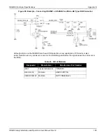
Some users may require additional drive strength on the PPS signal. The
Protection for Strobes (optional buffering for PPS)
on page 182 shows a suitable buffer that may be used.
R222 may be used to limit the drive strength of the PPS output buffer (if desired). This buffer has a
propagation delay of approximately 5-6 nanoseconds.
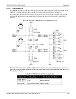
A similar ESD protection circuit to the one shown below should be used on any OEM638 Logic-level signal
that will be routed to an enclosure connector. (If an EVENT_IN or EVENT_OUT line is routed to an enclosure
connector the capacitance must be minimized—these signals may require buffering in some applications.)
Figure 91: Example - ESD Protection for Strobes (optional buffering for PPS)
The STATUS_RED, STATUS_GRN, ERROR and PV signals are generally used on enclosure products to
show the current status of the receiver. These signals may require a buffer to drive an LED. An example of a
suitable buffer circuit is shown below:

