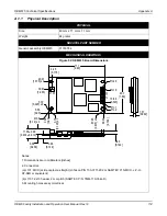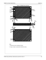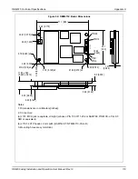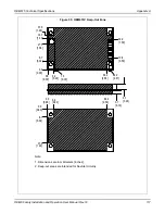
OEM615 Technical Specifications
Appendix A
OEM6 Family Installation and Operation User Manual Rev 12
118
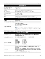
ENVIRONMENTAL
Operating Temperature
-40
C to +85
C
Storage Temperature
-55
C to +95
C
Humidity
MIL-STD-810G, Method 507.5 Procedure II (95%)
Random Vibration
MIL-STD 810G Method 514.6, Category 24 (7.7 g RMS)
Sinusoidal Vibration
IEC 60068-2-6 (5 g)
Bump
ISO 9022-31-06 (25 g)
Shock
Operating: MIL-STD-810G, Method 516.6, Procedure I (40 g)
Non-operating: MIL-STD-810G, Method 516.6, Procedure V (75 g)
POWER REQUIREMENTS
Voltage
+3.3 VDC ±5%
Allowable Input Voltage Ripple
100 mV p-p maximum
Power Consumption
<1.0 W typical, GPS L1/L2
1.1 W typical, GPS/GLONASS L1/L2
1.2 W typical, all on
Values can change with the number of satellites in view and the firmware
version. Use them as a guide for what you might expect but not as absolute
values.
In-Rush Power Consumption
6.0 A for less than 60
s (typical)
RF INPUT / LNA POWER OUTPUT
Antenna Connector
MCX female, 50
Acceptable RF Input Level
L1: -122 to -87 (signal) dBm, -161 to -141 (noise) dBm/Hz
L2: -126 to -93 (signal) dBm, -161 to -141 (noise) dBm/Hz
RF Input Frequencies
GPS L1:
1575.42 MHz
GPS L2:
1227.60 MHz
GLONASS L1:
1593-1610 MHz
GLONASS L2:
1237-1253 MHz
Galileo E1:
1575.42 MHz
BeiDou B1:
1561.098 MHz
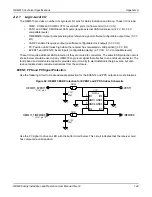
LNA Power
+5 VDC ±5%, 0-100 mA (supplied by card through center conductor of RF
connector).
The output current in all instances is limited to 100 mA and above an input
voltage of 6 V the output current limit is further reduced (derated) according to:
Iout < 0.1W/ (Vin - 5V)
where Vin is from 6 V to 12 V (J1101, Pin 1)

