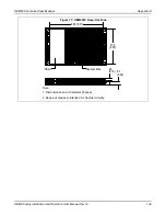
OEM628 Technical Specifications
Appendix D
OEM6 Family Installation and Operation User Manual Rev 12
155
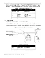
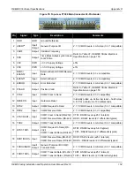
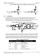
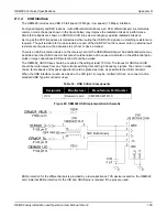
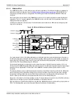
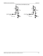
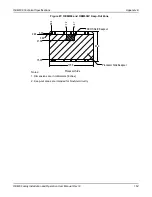
Figure 79: Top-view, P1502 Expansion 16-Pin Header
21 D-
Input/
Output
USB D-
90
Ω
differential pair, 5 V tolerant
22 D+
Input/
Output
USB D+
23 GND
GND
Ground Reference
–
24 GND
GND
Ground Reference
–
a. On power up, if pin 2 is LOW or not connected, COM1 is configured as RS-232. If pin 2 is high, COM1 is configured as RS-
422 (refer to
OEM6 Card Default Serial Port Configurations
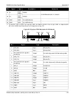
Pin
Signal
Type
Description
Comments
Pin
Signal
Type
Description
1
ETH_RD-
Input
Ethernet Rx-
2
Input
Ethernet Rx+
3
3V3 (for Ethernet magnetics
center tap)
Output
Rx centre tap power for Ethernet magnetics
4
Output
Ethernet Tx+
5
ETH_TD-
Output
Ethernet Tx-
6
3V3 (for Ethernet magnetics
center tap)
Output
Tx center tap power for Ethernet magnetics
7
LED_A
Output
Activity/Link
8
LED_B
Output
100 BT
9
GND
REF
GND
10
CAN1TX
Output
CAN1TX
11
CAN1RX
Input
CAN1RX
12
CAN2TX
Output
CAN2TX
13
CAN2RX
Input
CAN2RX
14
Reserved
Input
UID
15
VBUS
Input
VBUS
16
GND
REF
GND
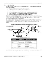
Pin 2
Pin 1
Pin 24
Pin 23
Pin 2
Pin 16
Pin 15
Pin 1


