Control System
51
Service Manual – Scrubtec R 253 - RA40
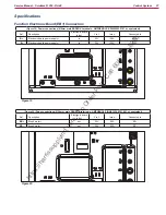
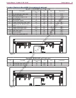
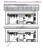
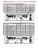
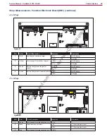
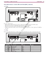
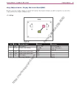
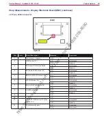
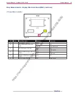
Shop Measurements - Display Electronic Board (EB2)
Measure and record the voltage at each of the function board pins Always use battery negative as your refer-
ence point for your black voltmeter lead
J1 - 6 Ways
Figure 44
REAR
J1
PIN
Color
Circuit Description
Measured
Comments
1
White
Power
23.1V
Key In (all condition)
2
Brown
Machine startup enabling
0V
Power Off (Timed out)
22.7V
Power On
3
Green
Display electronic board
4.5V
4
Yellow
Display electronic board serial -
4.0V
5
Grey
Power supply -
0.03V
Vac On
6
Power supply repetition -
No wire
https://harrissupplyind.com - To Order Parts Call 608-268-8080

