background image

Recovery System

74

Service Manual – Scrubtec R 253 - RA40

Removal and Installation

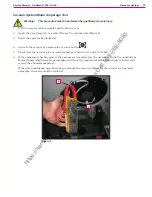
Vacuum System Motor Unit Disassembly/Assembly

Disassembly

1   Remove the operator key 

2   Disconnect the red battery connector 

3   If present, drain the recovery tank, then lift it 

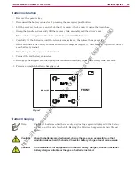
4   Disconnect the connector (A) (Figure 6) and remove the fastening clamp 

5   Unscrew the 3 screws (B) and remove the vacuum system motor unit (C) 

Figure 6

B

B

C

B

A

Assembly

6   Assemble the components in the reverse order of disassembly 

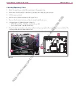
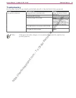
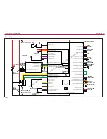
https://harrissupplyind.com - To Order Parts Call 608-268-8080

Содержание R 253 9087362020

Страница 1: ...ervice Manual Nilfisk R 253 9087362020 9087365020 Clarke RA40 9087363020 English 01 2015 revised 03 2016 2 Form No 9100000402 h t t p s h a r r i s s u p p l y i n d c o m T o O r d e r P a r t s C a l l 6 0 8 2 6 8 8 0 8 0 ...

Страница 2: ...8 Control System 19 Functional Description 19 Wiring Diagram 20 Component Locations 21 Troubleshooting 22 Function Electronic Board EB1 Alarm Codes 22 Super User Screen 27 Alarm Log Screen 27 Setting Screen 29 Hours Screen 31 System for Flow Rate Adjustment as Function of Speed 32 Removal and Installation 33 Function Electronic Board EB1 Removal Replacement 33 Display Board EB2 and Dashboard Instr...

Страница 3: ...ry Tank Cleaning 71 Troubleshooting 72 Vacuum System Motor Amperage Test 73 Removal and Installation 74 Vacuum System Motor Unit Disassembly Assembly 74 Container and Vacuum System Motor Disassembly Assembly 75 Specifications 78 Scrub System Disc 79 Functional Description 79 RPM Brush Reduction Function 79 Wiring Diagram 80 Component Locations 81 Brush Installation Removal 83 Troubleshooting 84 Br...

Страница 4: ...ments 109 Squeegee cleaning 109 Checking Replacing the Squeegee Blades 110 Troubleshooting 111 Removal and Installation 112 Squeegee Lifting Actuator Disassembly Assembly 112 Squeegee Tie Rod Disassembly Assembly 113 Specifications 114 Steering System 115 Functional Description 115 Component Locations 115 Specifications 116 Wheels Drive System 117 Functional Description 117 Wiring Diagram 118 Comp...

Страница 5: ...nance and repair procedure on the machine Other Reference Manuals Model Product Code User Manual Spare Parts List Nilfisk Scrubtec R 253 9087362020 9100000391 9100000392 Nilfisk Scrubtec R 253 full PKG 9087365020 Clarke RA40 9087363020 9100000394 Assembly Instructions Instruction Code Machines concerned Chemical Mixing System Kit 9100000953 Scrubtec R 253 RA40 Battery charger kit 9100001068 Scrubt...

Страница 6: ...ailer label here Serial Number Label Reference to Figure 1 The machine serial number and model name are marked on the plate see the example to the side Product code and year of production are marked on the same plate This information is useful when requiring ma chine spare parts Use the following table to write down the machine identification data Battery 24 Vdc Date code LpA 68 dB A Charg 100 240...

Страница 7: ...ning Do not wash the machine with direct or pressurized water jets max 2 Warning Do not use the machine on slopes with a gradient exceeding the specifications Symbols Note It indicates a remark related to important or useful functions Danger It indicates a dangerous situation with risk of death for the operator Warning It indicates a potential risk of injury for people or damage to objects Caution...

Страница 8: ...tage Do not pull or carry the machine by the battery charger cable and never use the battery charger cable as a handle Do not close a door on the battery charger cable or pull the battery charger cable around sharp edges or corners Do not run the machine on the battery charger cable Keep the battery charger cable away from heated surfaces Do not charge the batteries if the battery charger cable or...

Страница 9: ...ons scrupu lously Do not allow any object to enter into the openings Do not use the machine if the openings are clogged Always keep the openings free from dust hairs and any other foreign material which could reduce the air flow Do not remove or modify the plates affixed to the machine To manually move the machine the electromagnetic brake must be disengaged After moving the ma chine manually enga...

Страница 10: ...chine Transportation Warning Before transporting the machine make sure that All covers are closed The recovery tank and the detergent tank are empty The batteries are disconnected The ignition key is removed The machine is securely fastened to the means of transport h t t p s h a r r i s s u p p l y i n d c o m T o O r d e r P a r t s C a l l 6 0 8 2 6 8 8 0 8 0 ...

Страница 11: ...er Solution valve Brush deck Solution filter Solenoid valve Front steering wheel Squeegee Squeegee bumper wheels Solution drain and level check hose Solution tank Dumping recovery tank assembly EMERGENCY push button Seat Battery connector Recovery tank cover Squeegee hook Electromagnetic brake locking unlocking lever Figure 2 h t t p s h a r r i s s u p p l y i n d c o m T o O r d e r P a r t s C ...

Страница 12: ...ebris col lection grid Squeegee mounting hand wheels Squeegee support wheel Brush deck bumper wheel Rear driving wheels Battery charger Tank assembly and seat lifting handle Serial number plate technical data Chemical mix ing system detergent tank Electronic component compartment cover Batteries Tank assembly sup port rod Lifted recovery tank assembly and driver s seat Figure 3 h t t p s h a r r i...

Страница 13: ...operating information Vacuum system button One Touch Scrub ON OFF push button Reverse gear button Solution flow adjustment button Horn button Detergent percentage adjustment button Machine ignition key Figure 4 h t t p s h a r r i s s u p p l y i n d c o m T o O r d e r P a r t s C a l l 6 0 8 2 6 8 8 0 8 0 ...

Страница 14: ...DVM Amp clamp with possibility of making DC measurements Hydrometer Battery charge tester to check 12V batteries Static control wrist strap Dynamometric wrench set A copy of the User Manual and Spare Parts List of the machine to be serviced provided with the machine or available at www nilfisk com and www clarkeus com or other Nilfisk Clarke websites The following equipment is also available at Ni...

Страница 15: ...SO 5349 1 EN 60335 2 72 130 in s2 3 3 m s2 Vibration level at the operator s body ISO 5349 1 EN 60335 2 72 35 4 in s2 0 9 m s2 Maximum gradient when working 2 Drive system motor power 0 53 hp 400 W Drive speed variable 0 3 7 mi h 0 6 km h Vacuum system motor power 0 4 hp 310 W Vacuum system circuit capacity 39 in H2 O 1000 mm H2 O Brush motor power 0 6 hp 450 W Brush rotation speed 155 rpm Total p...

Страница 16: ...n 16 Service Manual Scrubtec R 253 RA40 Dimensions 50 0 in 1270 mm 28 3 in 720 mm 40 1 in 1020 mm 21 6 in 550 mm Figure 6 h t t p s h a r r i s s u p p l y i n d c o m T o O r d e r P a r t s C a l l 6 0 8 2 6 8 8 0 8 0 ...

Страница 17: ...ance For instructions on maintenance procedures see the following paragraphs Scheduled Maintenance Table Procedure Daily after using the machine Weekly Every six months Yearly Battery Charging Squeegee Cleaning Brush pad cleaning Recovery tank and debris tray cleaning and cover gasket check Chemical Mixing System cleaning and draining Squeegee blade check Solution filter cleaning Battery WET fluid...

Страница 18: ...port plate and deck mount Main support side member Gearmotor support plate and squeegee system mount Steering assembly column support plate and deck mount Gearmotor support plate and squeegee system mount Figure 1 Main support side member h t t p s h a r r i s s u p p l y i n d c o m T o O r d e r P a r t s C a l l 6 0 8 2 6 8 8 0 8 0 ...

Страница 19: ...ectronic board EB1 The display electronic board EB2 Display electronic board EB2 Flat cable from EB2 to EB4 serves mainly as an aggregator for all input signals buttons and outputs LEDs from the dashboard in strument electronic board EB4 Dashboard electronic board EB4 which it is connected to via 2 flat cables The ignition key SW1 is inserted in relevant slot on the steering column The display ele...

Страница 20: ...play electronic board serial Display electronic board serial Return from steering microswitch Microprocessor DASHBOARD ELECTRONIC BOARD EB4 FUNCTION BOARD EB1 SIGNAL CIRCUIT FUSE F2 DISPLAY BOARD EB2 J3 J2 J1 5 J1 1 J1 2 J1 3 5V J1 4 J1 5 J1 6 J1 7 J1 8 J1 9 J1 12 B B J1 4 J1 3 J1 2 J1 1 J4 1 J4 2 J4 3 J4 4 Enabling from battery charger Power supply from battery charger Battery charger enabling po...

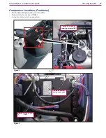
Страница 21: ...d instrument electronic board EB4 Flat cables from EB2 to EB4 Ignition Key SW1 Function electronic board EB1 Figure 2 Figure 3 Ignition key SW1 Dashboard instrument elec tronic board EB4 Display electronic board EB2 Flat cables from EB2 to EB4 h t t p s h a r r i s s u p p l y i n d c o m T o O r d e r P a r t s C a l l 6 0 8 2 6 8 8 0 8 0 ...

Страница 22: ...tronic board EB1 as indicated in the following tables Figure 5 General alarms Alarm on function electronic board FLASHING YELLOW RED LEDS Alarm code Description No Flashes Meaning Condition Effect Service Suggestions G2 EEPROM ERROR 2 EEPROM error EEPROM error Function block Default setting reset If the machine continues to function after G2 has been displayed this may have been caused by a signif...

Страница 23: ...G4 BATTERY LOW VOLTAGE 4 Undervoltage The battery voltage remains below 18 4V for over 10 seconds for WET CELL batteries 19 6V for GEL AGM batteries Function block 1 Check the battery voltage under no load conditions and under load Replace the faulty battery batteries if necessary 2 Recharge the batteries by performing a complete charging cycle G5 BATTERY OVERVOLTAGE 5 Excessive battery voltage Ba...

Страница 24: ...at the actuator and deck travel is not blocked by mechanical obstructions 3 If the problem persists replace the actuator F5 SQUEEGEE ACTUATOR FAILURE 5 SQUEEGEE ACTUATOR overcurrent Current greater than 4A detected for more than 1 second Vacuum function block 1 Check that there is no friction on the brush deck linkage lubricate if necessary 2 Check that the actuator and deck travel is not blocked ...

Страница 25: ...ectronic board T6 DRIVE MOTOR FAILURE 6 Overcurrent motor D C Drive system motor amperage greater than 1 5 times the value of the parameter see page 28 IMAX Drive blocked 1 Check that the gearmotor cables are not short circuited 2 Check that the motor of the gearmotor unit is not short circuited the impedance of the motor should be around 0 6 0 8 Ohm 3 If necessary replace the gearmotor unit motor...

Страница 26: ...voltage Battery voltage over 32V Battery charger block 1 Check the connections of the batteries and the voltage of the installed batteries 2 Disconnect and reconnect the battery charger C4 CHARGING TIME I EXPIRED Charging phase I expired Battery excessively discharged or at end of life cycle Battery charger block If the problem persists replace the batteries C5 CHARGING TIME II EXPIRED Charging ph...

Страница 27: ...to switch to the screen menu D 3 Press the vacuum system button E to access the alarm log screen F 4 To return to the menu screen D repeatedly press the One Touch button G Figure 6 A B C 1sec E G F D Each alarm See table of alarms in the Function Electronic Board Alarm Codes paragraph is stored along with the working hour machine operating time counter at which it occurred and all alarms are recor...

Страница 28: ...correct use by customer Risk of reduced battery life GC CHARGER DISCONN BEFORE END CYCLE Charging cycle interrupted before completion Disconnection of battery charger before stage IV battery symbol with 3 segments lit steadily Incorrect use by customer Risk of reduced battery life GD N CHARGING TIME LESS THAN 4 HOURS Charging phase duration N Number of hours from battery charger connection to comp...

Страница 29: ...100 P2 P3 Level 2 solution flow rate in relation to level 3 see System for Flow Rate Regulation as Function of Speed paragraph 0 50 100 P3 Level 3 solution flow rate 1 0 cl m 3 0 cl m 5 0 cl m P4 Level 4 enabling 2 8 l min regardless of speed OFF OFF ON XPRES Brush deck extra pressure enabling OFF ON ON FVMAX Maximum forward speed 10 100 100 RVMAX Maximum reverse speed 10 40 50 WSMIN Minimum worki...

Страница 30: ...em reduces the power to the driving wheel to keep the stability of the machine WARNING increasing this value increases the risk of machine overturning KG Lateral acceleration control constant 1 0 1 6 2 0 Engineering parameter connected to AMAX Do not change VS1 Brush 1 motor protection threshold A 20 30 50 This is the maximum current which can be supplied to the disc brush deck WARNING increasing ...

Страница 31: ...rating time counter screen E The operating time counter screen E function allows you to check the total accumulated hours of work for each machine subsystem F TOTAL counter machine running time G DRIVE counter drive system usage time H BRUSH counter brush rotation system usage time I VACUUM counter vacuum system usage time 4 To return to the screen menu D press the One Touch button J Figure 8 E A ...

Страница 32: ...d 2 are defined via the corresponding parameters P1 and P2 as a of level 3 For example for P1 25 and P2 50 P1 and P2 are respectively 25 and 50 of the reference flow rate P3 The default values the same as in the example above are summarized in the table with the corresponding flow rate values in liters per minute dependent on machine speed given as a reference Detergent flow as a function of speed...

Страница 33: ...ews and remove the upper cover 5 Remove the 2 screws and remove the function electronic board front cover 6 Disconnect the following connections Figure 9 A and B Electronic board power supply connection B and B C and D Brush motor connection BR and BR Figure 9 A B D C A B D C 7 Disconnect the following connections Figure 10 E and F Drive system motor connection M1 and M2 G and H Vacuum system moto...

Страница 34: ...con light and driver s seat sensor connection J3 K Battery charger connection J4 L Brush deck actuator connection J2 M Accessory connection J8 Figure 11 I I K K L L M M J J 9 Unscrew the 4 retaining screws N and carefully remove the function electronic board Figure 12 Figure 12 N N N N N N N N 10 Assemble the components in the reverse order of disassembly h t t p s h a r r i s s u p p l y i n d c ...

Страница 35: ...roup and disconnect the wiring harness connection B 5 At the workbench remove the 6 screws C Figure 14 6 Lift the cover of the dashboard instrument board D Figure 15 and recover the gasket E 7 Remove the screws F and remove the display electronic board G 8 Disconnect the connection H Figure 16 9 Disconnect the flat connections I and J from the display electronic board EB2 Figura 13 A B Figura 15 D...

Страница 36: ... the reverse order of disassembly and note the following Install the display electronic board EB2 and check the proper operation and function By carefully install the dashboard electronic board EB4 on the cover paying attention to the routing of the flat connections in the cover slots Figura 17 K L Figura 18 N M Warning The first batch of Display electronic board EB2 are equipped with an 8 way mal...

Страница 37: ...ax Connected to B Electronic board power supply in 24V 125A BAT B Electronic board power supply in 24V 125A BAT Figure 19 Figure 20 Drive connections Ø3 6mm male RADSOK terminals AMPHENOL P N N01 036 6501 001 or equivalent Ref Description Electronic board in out V ref I max Connected to BR Brush motor out 24V 50A M1 BR Brush motor out 24V 50A M1 Figure 20 h t t p s h a r r i s s u p p l y i n d c ...

Страница 38: ...x Connected to M1 Drive system motor out 0 24V 70A M3 M2 Drive system motor out 0 24V 70A M3 Figure 21 Figure 22 Vacuum connections 2 way male parallel faston connectors 6 3x0 8 spacing 6 5mm Ref Description Electronic board in out V ref I max Connected to VA Vacuum system power supply out 16 24V 30A M2 VA Vacuum system power supply out 0V 30A M2 Figure 22 h t t p s h a r r i s s u p p l y i n d c...

Страница 39: ... power supply out 24V 3A EB2 1 7 Enabling input from display electronic board in 24V 3A EB2 2 8 Display electronic board serial in out 5V 1A EB2 3 9 Display electronic board serial in out 0V 1A EB2 4 10 Pedal power supply out 24V 1A PED 1 11 Return from pedal in 0 5V 1A PED 2 12 Return from steering microswitch in 0V 1A SW4 Figure 23 Figure 24 J2 MOLEX MINIFIT type 2 ways vertical PIN Description ...

Страница 40: ... actuator power supply out 0 24V 8A M6 5 Return from driver s seat microswitch In 0V 1A SW3 6 Auxiliary power supply out 24V 1A BE1 Figure 25 Figure 26 J4 MOLEX MINIFIT type 4 ways vertical PIN Description Electronic board in out V ref I max Connected to 1 Enabling from battery charger in 24V 1A CH 1 2 Power supply from battery charger in 24V 1A CH 2 3 Battery charger enabling power supply out 24V...

Страница 41: ...iption Electronic board in out V ref I max Connected to 1 Power supply for water level sensor out 24V 1A S1 1 2 Water level sensor return in 0V 1A S1 2 3 Power supply for water level sensor out 0V 1A S1 3 Figure 27 Figure 28 J6 JUMPER 2 ways vertical Figure 28 h t t p s h a r r i s s u p p l y i n d c o m T o O r d e r P a r t s C a l l 6 0 8 2 6 8 8 0 8 0 ...

Страница 42: ...e 29 Figure 30 J8 TYMOLEX MINIFIT type 10 ways vertical PIN Description Electronic board in out V ref I max Connected to 1 Solenoid valve power supply out 0V 1A EV1 2 Detergent pump power supply out 0V 1A M4 3 Electromagnetic brake output out 0V 1A BRK 4 Opt power supply out 0V 1A USB 5 DECK configurator return in 0V 1A J4 10 6 Solenoid valve power supply out 24V 1A EV1 7 Detergent pump power supp...

Страница 43: ... button P3 in 0V 1A 3 EDS button P2 in 0V 1A 4 DETERGENT MIX button P1 in 0V 1A 5 BRUSH EXTRAPR button P4 in 0V 1A 6 VACUUM button P5 in 0V 1A 7 BRUSH RELEASE button P6 in 0V 1A 8 ON OFF button P0 in 0V 1A 9 REVERSE GEAR button P7 in 0V 1A 10 INCREASE SPEED button P8 in 0V 1A 11 DECREASE SPEED button P9 in 0V 1A 12 Dashboard configurator in 0V 1A Figure 31 J3 FCI DUFLEX 2 54 pitch 6 way male pins ...

Страница 44: ...on Electronic Board EB1 Battery volts at battery key on 24 55V 23 5V Vac on high Power Supply Figure 32 PIN Color Description Measured Comments B Red Electronic board power supply 23 4V Measured B to B Vac on high B Black Electronic board power supply 23 4V Measured B to B Vac on high Brush Motor Figure 33 PIN Color Description Measured Comments BR Red Brush motor 23 5V Measured to BR normal scrub...

Страница 45: ...escription Measured Comments M1 White Drive system motor 21 7V FWD Measured M1 to M2 at Max speed 9 7V REV M2 Black Drive system motor 21 7V FWD Measured M1 to M2 at Max speed 9 7V REV Vacuum Motor Figure 35 PIN Color Description Measured Comments VA Red Vacuum system power supply 23 2V Measured VA to VA VA Blue Vacuum system power supply 23 2V Measured VA to VA h t t p s h a r r i s s u p p l y i...

Страница 46: ...V Gray Operator Key 1 21V Yellow Super User Key 5 Black External power supplies 0 03V Vac On 6 White Display electronic board power supply 23 1V Key In all condition 7 Brown Enabling input from display electronic board 0V Power Off Timed out 22 7V Power On 8 Green Display electronic board serial 4 5V 9 Yellow Display electronic board serial 4 0V 10 Violet Pedal power supply 23 7V 11 Vi Blk Return ...

Страница 47: ...38 PIN Color Circuit Description Measured Comments 1 Br Blk Squeegee actuator power supply 23V At rest 23 7V Extending Squeegee down 0 07V Retracting Squeegee up 2 Or Blk Driver s seat microswitch power supply 0 02V On or off seat 3 Wh Blk Auxiliary power supply Beacon 0V 4 Bl Blk Squeegee actuator power supply 0V At rest 0 08V Extending Squeegee down 23 9V Retracting Squeegee up 5 Or Blk Return f...

Страница 48: ...Charging 3 Brown Battery charger enabling power supply 24 4V Not Charging 26V Charging 4 Green Battery charger data communication 0 01V Not Charging 4 59V Charging J5 3 Ways Figure 40 PIN Color Circuit Description Measured Comments 1 Brown Power supply for water level sensor 21 6V 2 Black Water level sensor return 4 9V 1 2 solution tank level 0 03V 1 2 solution tank level 3 Blue Power supply for w...

Страница 49: ... set for EcoFlex Is there a measurable voltage on either of the pins when not jumped Yes 4 98v on pin near the LEDS on the board J7 6 Ways Measured machine did not have a wiring connector Measurements were taken at each pin on the board Figure 42 PIN Color Circuit Description Measured Comments 1 Red 24V power supply 24 6V 2 5V power supply 5 00V 3 Yellow iButton input 4 98V 4 Blue External time co...

Страница 50: ...off 3 Wh Blk Electromagnetic brake output 24 1V Not energized stationary 0 7V Energized moving 4 Black Opt power supply No wire 5 Green DECK configurator return 0V Loop not cut 6 Brown Solenoid valve power supply 24 2V 7 Grey Detergent pump power supply 24 2V 8 White Electromagnetic brake output 24 2V 9 Red Opt power supply No wire 10 Green Power supply for DECK configurator 0V Loop not cut h t t ...

Страница 51: ...J1 6 Ways Figure 44 REAR J1 PIN Color Circuit Description Measured Comments 1 White Power supply 23 1V Key In all condition 2 Brown Machine startup enabling 0V Power Off Timed out 22 7V Power On 3 Green Display electronic board serial 4 5V 4 Yellow Display electronic board serial 4 0V 5 Grey Power supply 0 03V Vac On 6 Power supply repetition No wire h t t p s h a r r i s s u p p l y i n d c o m T...

Страница 52: ... 0 03V Pressed 4 DETERGENT MIX button P1 3 1V Not pressed 0 1V Pressed 5 BRUSH EXTRAPR button P4 3 1V Not pressed 0 07V Pressed 6 VACUUM button P5 3 1V Not pressed 0 06V Pressed 7 BRUSH RELEASE button P6 3 1V Not pressed 0 04V Pressed 8 ON OFF button P0 22 1V Not pressed 0 02V Pressed 9 3 1V 10 3 1V 11 REVERSE GEAR button P7 Blue models only 3 1V Not pressed 0 06V Pressed 12 Dashboard configurator...

Страница 53: ...nts 1 Power supply common 0 007V 2 BRUSH RELEASE function LED LD3 0 01V Off 0 9V When flashing red 3 VACUUM function LED LD2 0 01V Off 2 0V Steady green 4 BRUSH EXTRAPR funct LED red LD1R 0 01V Off 2 0V Steady red 5 BRUSH EXTRAPR funct LED green LD1V 0 01V Off 6 SPOT function LED LD4 2 0V Steady green h t t p s h a r r i s s u p p l y i n d c o m T o O r d e r P a r t s C a l l 6 0 8 2 6 8 8 0 8 0...

Страница 54: ...tion allows the battery charger charging curve to the be set directly from the machine dash board and to view the operational state of the battery charger during charging directly on the dashboard display Battery Charger When the battery charger CH is connected to the power supply it provides a 24V on J4 2 in this con dition the electronic board EB1 disables all the con trol and functions except t...

Страница 55: ... Battery charger data communication B B C1 C1 C2 A 24V BATTERIES BAT SIGNAL CIRCUIT FUSE F2 BATTERY CONNECTOR MAIN BATTERY CONNECTOR BATTERY CONNECTOR BATTERY CHARGER CH FUNCTION ELECTRONIC BOARD EB1 FUNCTION ELECTRONIC BOARD FUSE F1 Figure 1 Optional for BASIC version Version without on board battery charger h t t p s h a r r i s s u p p l y i n d c o m T o O r d e r P a r t s C a l l 6 0 8 2 6 8...

Страница 56: ...use F1 Battery charger CH Battery connections Batteries BAT Battery connector C1 Batteries BAT Battery connector C1 Battery connections Figure 2 Function electronic board EB1 Function electronic board fuse F1 Signal circuit fuse F2 Battery charger CH Figure 3 h t t p s h a r r i s s u p p l y i n d c o m T o O r d e r P a r t s C a l l 6 0 8 2 6 8 8 0 8 0 ...

Страница 57: ...ry charger connector C2 J4 Bridge for without or broken on board battery charger On board battery charger connector C2 Figure 4 Figure 5 J4 bridge connector for without or broken on board battery charger h t t p s h a r r i s s u p p l y i n d c o m T o O r d e r P a r t s C a l l 6 0 8 2 6 8 8 0 8 0 ...

Страница 58: ...ion Min Value Factory Setting Max Value BAT Installed battery type 0 1 5 3 Press the One Touch button D or the vacuum system button E to modify the value of the BAT parameter as per the following table Code BAT Value Installed battery type 0 WET Wet cell batteries 1 GEL AGM Generic GEL or AGM batteries 2 GEL DISCOVER DISCOVER brand GEL batteries 3 GEL OPTIMA OPTIMA brand GEL batteries 4 GEL EXIDE ...

Страница 59: ...charging disconnect the battery charger from the electrical mains and from the battery red connector 5 Connect the battery connector to the machine 6 Disengage the support rod then grasp the handle and carefully lower the recovery tank assembly Battery charging with battery charger installed on the machine 7 Plug the battery charger into the electrical mains the mains voltage and frequency must be...

Страница 60: ...lace the protection cap on each terminal 9 Connect the red battery connector 10 Disengage the support rod then grasp the handle and carefully lower the recovery tank assembly 11 Perform a complete battery charging cycle Figure 7 BACK FRONT Battery Charging Note Charge the batteries when there is only one flashing segment displayed in the battery symbol or at the end of each shift Keeping the batte...

Страница 61: ... remove the upper cover 5 Remove the 2 screws and remove the electronic board front cover 6 Check replace the following fuses Figure 8 F1 100A midi fuse Function electronic board A F2 3A blade fuse Signal circuits B 7 Place the function electronic board assembly in its housing tighten the mounting screws and install the electronic component compartment cover Figure 8 B B A A h t t p s h a r r i s ...

Страница 62: ...Check the battery no load voltage The battery charger CH is broken Replace To restore the machine functioning disabling the on board battery charger with sthe bridge connector on the J4 connection placed on the function electronic board EB1 The wiring harness is cut or pressed or short circuited Repair The ignition key SW1 is broken Replace Note A damage to the battery charger or its connections c...

Страница 63: ...length x width x height 13 7x14 1x11 in 350x360x280 mm Standard batteries 2 Discover 12V 105Ah Standard battery run time capacity 2 5 h Battery charger Input voltage 100 240Vac 50 60Hz 24Vdc 13A Charging procedure by microprocessor Efficiency 85 Environmental protection class IP30 h t t p s h a r r i s s u p p l y i n d c o m T o O r d e r P a r t s C a l l 6 0 8 2 6 8 8 0 8 0 ...

Страница 64: ... s seat microswitch Auxiliary power supply Squeegee actuator power supply Driver s seat microswitch power supply DECK configurator return Squeegee actuator power supply Electromagnetic brake output Opt power supply Detergent pump power supply Electromagnetic brake output Solenoid valve power supply Detergent pump power supply Deck actuator power supply Solenoid valve power supply Drive system moto...

Страница 65: ...y brake Cap Refill cap Hose Pump chemical mix Sensor water level Support sensor Hardware BATTERY CHARGER KIT EU model only Charger extention UK EU Cable tie plug Charger battery Support battery charger Hardware WASTE BASKET KIT EU model only Support Basket Hardware h t t p s h a r r i s s u p p l y i n d c o m T o O r d e r P a r t s C a l l 6 0 8 2 6 8 8 0 8 0 ...

Страница 66: ...el only Support mop Spacer for support Tool holder Hardware ENHANCED VACUUM SYSTEM MOTOR KIT EU model only Vacuum motor assembly Hardware WATER FILLER HOSE KIT Support rubber for filling hose Hose filling Hardware h t t p s h a r r i s s u p p l y i n d c o m T o O r d e r P a r t s C a l l 6 0 8 2 6 8 8 0 8 0 ...

Страница 67: ...ion Illustration STOP WATER KIT Solution cap Fitting quick 1 2 gas Valve water stop Support Hardware BEACON LIGHT KIT Support Beacon Hardware USB KIT USB cable Plate Hardware h t t p s h a r r i s s u p p l y i n d c o m T o O r d e r P a r t s C a l l 6 0 8 2 6 8 8 0 8 0 ...

Страница 68: ...0 Description Illustration TRACKCLEAN KIT Trackclean sensor assy Mounting cradle Trackclean system IButton Trackclean reader kit reader 2 keys Trackclean system RDR h t t p s h a r r i s s u p p l y i n d c o m T o O r d e r P a r t s C a l l 6 0 8 2 6 8 8 0 8 0 ...

Страница 69: ...loat in the vacuum grid stops vacuum system motor M2 from collecting any liquids The vacuum duct for connecting the vacuum grid to the vacuum system motor M2 is inside the recovery tank cover When the automatic float closes and shuts down the vacuum system the vacuum system motor noise will increase and the floor will not be dried The gasket on the input of the vacuum system motor allows full func...

Страница 70: ...2 Container with debris collection grid Vacuum grid with automatic shut off float Cover gasket Container with debris col lection grid Recovery tank Recovery tank cover Figure 2 Vacuum grid with auto matic shut off float Vacuum system motor M2 Squeegee vacuum hose Recovery water drain hose Figure 3 Motor protection case h t t p s h a r r i s s u p p l y i n d c o m T o O r d e r P a r t s C a l l 6...

Страница 71: ...l it on the vacuum hose 7 Reinstall the debris collection tank on the rigid tube in the tank 8 Check the condition of the tank cover gasket E Note The gasket E creates the vacuum in the tank that is necessary to vacuum up the recovery water 9 If necessary replace the gasket E by removing it from its housing F When fitting the new gasket position the joint G in the area shown in the figure 10 Check...

Страница 72: ...rage Suction of dirty water is insufficient or non existent Activation of automatic float shut off Drain the recovery tank Debris collection filter dirty Clean Vacuum grid with automatic shut off float dirty Clean Tank cover not correctly positioned Adjust Tank cover gasket damaged or not working correctly Clean or replace Vacuum system motor container dirty Clean Vacuum seals damaged or not worki...

Страница 73: ...vacuum button 5 Check that the vacuum system motor amperage is between 13 and 17A at 24V 6 If the amperage is higher remove the vacuum system motor see the procedure in the Vacuum System Motor Disassembly Assembly paragraph and check the condition of all its components to detect and correct the abnormal amperage If the above mentioned procedures do not produce the correct readings for the vacuum s...

Страница 74: ...tery connector 3 If present drain the recovery tank then lift it 4 Disconnect the connector A Figure 6 and remove the fastening clamp 5 Unscrew the 3 screws B and remove the vacuum system motor unit C Figure 6 B B C B A Assembly 6 Assemble the components in the reverse order of disassembly h t t p s h a r r i s s u p p l y i n d c o m T o O r d e r P a r t s C a l l 6 0 8 2 6 8 8 0 8 0 ...

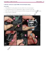
Страница 75: ... At the workbench remove the terminals lock A Figure 7 from the connector B 3 With a little screwdriver C move the splane lock D for disengaging the terminals from the connector 4 Remove the two terminals E 5 Carefully slightly lift the splane lock D previously pressed to restore it Figure 7 D C A D B E h t t p s h a r r i s s u p p l y i n d c o m T o O r d e r P a r t s C a l l 6 0 8 2 6 8 8 0 8...

Страница 76: ...nues 6 Remove the clamp F Figure 8 7 Remove the 4 screws G and remove the cover H Figure 8 F G H 8 Remove the soundproofing I Figure 9 and J 9 Remove the protection K to reach the vacuum system motor L Figure 9 K L J I h t t p s h a r r i s s u p p l y i n d c o m T o O r d e r P a r t s C a l l 6 0 8 2 6 8 8 0 8 0 ...

Страница 77: ... any dirt that has settled and check all gaskets J Figure 10 for wear replace if necessary Figure 10 J J J Assembly 11 Check that all components are reassembled with the correct polarity and orientation 12 Assemble the components in the reverse order of disassembly h t t p s h a r r i s s u p p l y i n d c o m T o O r d e r P a r t s C a l l 6 0 8 2 6 8 8 0 8 0 ...

Страница 78: ... capacity 18 5 US gal 70 liters Vacuum system motor technical data Power 0 4 hp 310 W Insulation Class H Voltage VDC 24V Bearing impeller side CW chemically resistant sealing Insulation materials and wires UL recognized Vacuum circuit capacity 39 in H2 O 1000 mm H2 O h t t p s h a r r i s s u p p l y i n d c o m T o O r d e r P a r t s C a l l 6 0 8 2 6 8 8 0 8 0 ...

Страница 79: ...ex tra pressure function off If the overload persists the brush stops The overload is detected by monitoring the current flow sum on the brush motor The current is mea sured by verifying the voltage drop through the brush system fuse F1 If the voltage drop reaches the val ue stored in the parameter VS2 default 70 mV the display shows the alarm message WARNING ALARM F2 and if the overload persists ...

Страница 80: ...r normal work condition 3 EXTRAPRESSURE fully extended end of stroke deck on the floor with extra pressure given pressing the actuator integrated spring The actuator is powered at 50 PWM about 12Vdc near the end of strokes or during the machine switch on reset feature otherwise at 100 PWM 24Vdc The machine switch on reset feature moves the actuator from the position where it was the last time the ...

Страница 81: ... Brush motor M1 Disc brush deck Deck raising levers Brush deck support Drive hub Deck raising levers Brush motor M1 Brush deck support Disc brush deck Figure 2 Figure 3 Drive hub h t t p s h a r r i s s u p p l y i n d c o m T o O r d e r P a r t s C a l l 6 0 8 2 6 8 8 0 8 0 ...

Страница 82: ... lowering actuator M5 Function electronic board EB1 Actuator system wiring connection Figure 4 Brush deck lifting lowering actuator M5 Figure 5 Actuator system wiring connection Function electronic board EB1 h t t p s h a r r i s s u p p l y i n d c o m T o O r d e r P a r t s C a l l 6 0 8 2 6 8 8 0 8 0 ...

Страница 83: ...e pad holder B under the deck 3 Turn the ignition key to I 4 Press the One Touch button to lower the deck onto the brush 5 To engage the brush press the drive pedal shortly if necessary repeat the procedure until the brush is engaged 6 To remove the brush lift the deck by pressing the One Touch button then manually release the brush from the hub by turning it abruptly in its normal rotation direct...

Страница 84: ...the brush and clean it Faulty brush motor Repair or replace Wiring damaged Repair It is not possible to lift lower the brush See the chapter Control System Function Electronic Board EB1 Error Codes Deck lifting lowering actuator M5 broken Replace Break in actuator wiring Check the connections according to the instructions in the Electrical System chapter Troubleshooting paragraph Function electron...

Страница 85: ...river s seat sensor 9 Activate the brush by pressing the accelerator pedal then check that the brush motor amperage is between 3 and 4A at 20V 10 Deactivate the brush by releasing the accelerator pedal and raise the brush deck by pressing the One Touch button 11 Remove the amp clamp C 12 If the amperage is higher perform the following procedures to detect and correct the abnormal amperage Check th...

Страница 86: ...d it for more than 1 second to activate the brush extra pressure function 6 Lift the recovery tank assembly and the driver s seat 7 Switch off the machine and disconnect the battery connector 8 Disassemble the electronic component compartment cover and the function electronic board panel 9 Remove the 4 screws C and remove the actuator plate D Figure 7 D C B A 10 Remove the screw E Figure 8 and rel...

Страница 87: ...ts suitable for the purpose 12 Remove the 4 screws J Figure 9 from the raising levers K 13 Lift the machine body L and disconnect the electrical wiring harness M from the brush motor then remove the brush deck N under the machine body Figure 9 N M L J K Assembly 14 Assemble the components in the opposite order they were removed in ensuring the brush motor power supply cable polarities are correct ...

Страница 88: ... remove the carbon brushes D 6 Check the carbon brushes D for wear The carbon brushes are worn out when They do not make sufficient contact with the armature of the brush motor due to their wear When their contact surface is not intact When the residual stroke is below 0 12 in 3 mm When the thrust spring etc is broken 7 Replace the carbon brushes as an assembly Reassembly 8 Assemble the components...

Страница 89: ...rush motor 3 Use a puller to remove the brush hub B 4 Remove the screws C 5 Remove the brush motor D 6 Recover the key E Assembly 7 Assemble the components in the reverse order of disassembly Note For further information on deck components see the Spare Parts List Figure 11 A E B C D h t t p s h a r r i s s u p p l y i n d c o m T o O r d e r P a r t s C a l l 6 0 8 2 6 8 8 0 8 0 ...

Страница 90: ... Switch off the machine and disconnect the battery connector 7 Disassemble the electronic component compartment cover and the function electronic board panel 8 Disconnect the actuator connection C on the function electronic board D 9 Remove the 4 screws E and remove the actuator plate F Figure 12 F D E C B A 10 Remove the screw G Figure 13 and release the actuator lower pin H 11 Disassemble the ac...

Страница 91: ...mm 2 5 0 6 in Brush distance from the floor when lifted 1 6 in 40 mm Brush motor power 0 6 hp 450 W Brush rotation speed 155 rpm Protection class IP 20 Insulation class F Actuator technical data Spring load 105 155 N Regulated travel 2 6 in 66 mm Total travel 3 6 in 98 mm Maximum speed 16 mm s Voltage 24V No load current Amps max 0 5 A Full load current Amps max 3 A Stall Amps 5 5 A Protection cla...

Страница 92: ...fined by the operator via the buttons on the dashboard instrument elec tronic board EB4 Solution flow levels 1 2 and 3 regulate the flow of so lution on the basis of the machine speed so as to keep the quantity of solution dispensed per square metre of floor treated constant for further details and modifi cations see the corresponding paragraph in the chap ter Control System Located centrally belo...

Страница 93: ...mes of opening of the solenoid valve EV1 and the detergent pump M4 are adjusted to maintain this flow more constant Figure 1 The water level sensor is capacitive with NPN output output 0 Volt with water floating without water Full Empty Solution tank With sensor Without sensor Solution flow to the brush Litre min Figura 1 J5 1 J5 2 J5 3 FUNCTION ELECTRONIC BOARD EB1 WATER LEVEL SENSOR SW1 24V B 0V...

Страница 94: ...sensor Water level sensor return Power supply for water level sensor Detergent pump power supply Solenoid valve power supply Detergent pump power supply FUNCTION ELECTRONIC BOARD EB1 SOLENOID VALVE EV1 CHEMICAL MIXING SYSTEM PUMP M4 SOLUTION LEVEL SENSOR SW1 J8 6 Solenoid valve power supply Figure 3 h t t p s h a r r i s s u p p l y i n d c o m T o O r d e r P a r t s C a l l 6 0 8 2 6 8 8 0 8 0 ...

Страница 95: ...on drain and level check hose Solution valve Solution filter Solenoid valve EV1 Solution tank filler plug Water removable filler hose Solution tank Solution drain and level check hose Figure 4 Figure 5 Solution filter Solenoid valve EV1 Solution valve h t t p s h a r r i s s u p p l y i n d c o m T o O r d e r P a r t s C a l l 6 0 8 2 6 8 8 0 8 0 ...

Страница 96: ...ing System detergent pump M4 Water level sensor S1 Battery compartment liquid drain hole Figure 6 Battery compartment liquid drain hole Plug with detergent supply hose Chemical Mixing Sys tem detergent tank Chemical Mixing Sys tem detergent pump M4 Water level sensor S1 h t t p s h a r r i s s u p p l y i n d c o m T o O r d e r P a r t s C a l l 6 0 8 2 6 8 8 0 8 0 ...

Страница 97: ... the operator key has been removed 3 Close the solution tank valve 4 Remove the transparent cover A Figure 7 retrieve the gasket B then remove the filter strainer C 5 Wash and rinse them with water then refit them carefully onto the filter support D 6 Open the solution tank valve A C B D Figure 7 h t t p s h a r r i s s u p p l y i n d c o m T o O r d e r P a r t s C a l l 6 0 8 2 6 8 8 0 8 0 ...

Страница 98: ... Lift the recovery tank assembly and the driver s seat 6 Unscrew the plug A Figure 8 from the detergent tank B 7 Remove the tank 8 Rinse and wash out the tank with clean water in the appointed disposal area 9 Replace the detergent tank B as shown in the figure then refit the plug A 10 When the detergent tank has been drained it may be necessary to drain the Chemical Mixing System too see procedure...

Страница 99: ...detergent remained on the floor 6 Remove the operator key 7 Lift the recovery tank assembly and the driver s seat then check that the detergent tank hose is empty otherwise perform steps 2 to 6 again Note The draining cycle lasts about 30 seconds then the vacuum function automatically turns on which allows to remove the detergent remained The draining cycle can also be performed with the detergent...

Страница 100: ...ection Presence of debris in solution tank blocking the outlet hole Clean the tank Presence of debris in the solution hose blocking the passage of the liquid Clean the hoses Function electronic board EB1 faulty Replace Display electronic board EB2 faulty Replace Dashboard instrument electronic board EB4 faulty Replace The solution reaches the brush also when the machine is off Presence of dirt or ...

Страница 101: ...ean the tank There is debris in the detergent hoses clogging the detergent flow Clean the hoses Function electronic board EB1 faulty Replace Display electronic board EB2 faulty Replace Dashboard instrument electronic board EB4 faulty Replace The Chemical Mixing System detergent is reaching the brush even with the machine off The pump M1 is broken Replace The one way valve is broken Replace Water i...

Страница 102: ...tment percentage detergent button B 2 Press hold 1 second the reverse button C to switch to the screen menu D Figura 10 A B C 1sec D 3 With the solution tank more than half full the symbol displayed is A Figure 11 4 With the solution tank less than half full the symbol displayed is B Figure 11 A B h t t p s h a r r i s s u p p l y i n d c o m T o O r d e r P a r t s C a l l 6 0 8 2 6 8 8 0 8 0 ...

Страница 103: ... Turn the ignition key to I 5 Lower the brush deck by pressing the One Touch button 6 Switch off the machine and disconnect the battery connector 7 Unscrew and disconnect the connection B 8 Remove the elastic clamp C and disconnect the detergent supply hose D from the solenoid valve 9 Disassemble the solenoid valve E Assembly 10 Assemble the components in the reverse order of disassembly Figure 12...

Страница 104: ...then disassemble the electronic component compartment cover 4 Disconnect the connectors A Figure 13 the tank hose B and brush hose C 5 Unscrew the two screws D and remove the detergent pump E Assembly 6 Assemble the components in the reverse order of disassembly ensuring the supply hoses B and C are correctly fitted on the detergent pump Figure 13 B D C D E A h t t p s h a r r i s s u p p l y i n ...

Страница 105: ...ery tank assembly and the driver s seat then disassemble the electronic component compartment cover 4 Unscrew the screw A Figure 13 and remove the sensor holder B 5 Unscrew the two screws C and remove the water level sensor D Assembly 6 Assemble the components in the reverse order of disassembly Figure 13 C D A B h t t p s h a r r i s s u p p l y i n d c o m T o O r d e r P a r t s C a l l 6 0 8 2...

Страница 106: ...0 Solution tank capacity 18 5 US gal 70 liters Solution flow values 0 75 cl m 1 5 cl m 3 0 cl m 2 8 L min if enabled Chemical Mixing System kit tank capacity 1 3 US gal 5 L Chemical Mixing System kit detergent percentage setting Ratio 1 500 1 33 0 25 3 h t t p s h a r r i s s u p p l y i n d c o m T o O r d e r P a r t s C a l l 6 0 8 2 6 8 8 0 8 0 ...

Страница 107: ...ign and the central duct make it easy for the squeegee to clear the water The rear blade edge is smooth All 4 functional edges of each blade can be used before it needs replacing The squeegee is lifted and lowered by an actuator M6 located in the solution tank compartment It is acti vated at the same time as the brush deck The squeegee actuator M6 has 2 limit microswitches not accessible Every tim...

Страница 108: ...ng Squeegee adjusting knob Squeegee support Mounting handwheels Actuator M6 Tie rods Squeegee adjusting knob Squeegee support Mounting handwheels Bumper wheels Tie rods Squeegee reset spring Actuator M6 Squeegee blades Figure 2 h t t p s h a r r i s s u p p l y i n d c o m T o O r d e r P a r t s C a l l 6 0 8 2 6 8 8 0 8 0 ...

Страница 109: ... machine on a level floor 2 Ensure that the machine is off and the operator key has been removed 3 Loosen the handwheels and remove the squeegee 4 Wash and clean the squeegee In particular clean the compartments A Figure 2 and the hole B Check that the front blade C and the rear blade D are integral and free from cuts and lacerations if necessary replace them 5 Assemble in the reverse order of dis...

Страница 110: ...g intact corners If the other corners are worn too replace the blade according to the following procedure Using the tab F release and remove the elastic strap G from the fasteners H then turn or replace the rear blade D Install the blade in the reverse order of re moval Unscrew the handwheels I and remove the strap J then turn or replace the front blade C Install the blade in the reverse order of ...

Страница 111: ...e blade lips damaged or worn Replace Squeegee not balanced Adjust with the relevant handwheel The squeegee cannot be lifted lowered See the chapter Control System Function Electronic Board EB1 Error Codes Squeegee lifting lowering actuator M6 broken Replace Break in actuator wiring Check the connections according to the instructions in the Electrical System chapter Troubleshooting paragraph Functi...

Страница 112: ...ved 4 Disassemble the retaining spring A Figure 4 retrieve screws and washers 5 Disconnect the squeegee power supply connection B 6 Remove the two screws C and the screw D then lift the actuator plate E 7 Remove the nut F and retrieve the screw G 8 Replace the actuator H Assembly 9 Assemble the components in the reverse order of disassembly Figure 4 G F H B D E C A h t t p s h a r r i s s u p p l ...

Страница 113: ...erator key has been removed 4 Unscrew the nuts A Figure 5 retrieve the washers and spacers 5 Carefully disassemble the tie rod B from the studs by paying attention to the squeegee reset spring C Assembly 6 Assemble the components in the reverse order of disassembly and note the following Assemble the tie rod B by loading it with the squeegee reset spring C Figure 5 A B C A h t t p s h a r r i s s ...

Страница 114: ... Squeegee width 28 3 in 720 mm Actuator technical data Spring load 70 100 N Total travel 3 in 77 mm Maximum speed 16 mm s Voltage 24V No load current Amps max 0 5 A Full load current Amps max 3 A Stall Amps 5 5 A Protection class IP 44 Insulation class A h t t p s h a r r i s s u p p l y i n d c o m T o O r d e r P a r t s C a l l 6 0 8 2 6 8 8 0 8 0 ...

Страница 115: ...steering system managed using the accelerometer built into the func tions board EB1 see the wheel traction system chapter When necessary the anti skid control sensor reduces the speed to a safe speed when turning in order to avoid sudden skidding thus increasing machine stability in all conditions The system activation is shown by the icon on the display Component Locations Front fairing Steering ...

Страница 116: ...1 3 N mm2 Front wheel maximum turning angle 70 Steering turning angle 230 Steering reduction rate 3 1 Machines have been tested under the following conditions Battery maximum size Maximum brush and squeegee size Full detergent tank Optional equipment installed Wheel weight checked Print on the floor checked on cement for each single wheel Result expressed as maximum value for rear wheels h t t p s...

Страница 117: ...m Codes paragraph in Con trol System chapter and the drive system is inhib ited When the drive pedal returns to the rest position the alarm is automatically deactivated without having to turn the machine off and on again When the drive pedal is pressed the function elec tronic board EB1 powers the electromagnetic brake to release the wheel then activates the gearmotor M3 with a proportional voltag...

Страница 118: ...lay electronic board serial Return from steering microswitch Pedal power supply Return from pedal J1 1 J1 2 J1 3 Return from driver s seat microswitch Driver s seat microswitch power supply Electromagnetic brake output Electromagnetic brake output Drive system motor Drive system motor J1 4 J1 3 J1 2 J1 1 Microprocessor FUNCTION ELECTRONIC BOARD EB1 DISPLAY ELECTRONIC BOARD EB2 ELECTROMAGNETIC BRAK...

Страница 119: ...witch SW3 Driver s seat microswitch connector Drive pedal with potentiometer RV1 Driver s seat micro switch SW3 Figure 2 Driver s seat micro switch connector Figure 3 Drive pedal with po tentiometer RV1 h t t p s h a r r i s s u p p l y i n d c o m T o O r d e r P a r t s C a l l 6 0 8 2 6 8 8 0 8 0 ...

Страница 120: ...40 Component Locations continues Driving wheels Gearmotor unit M3 Electromagnetic brake BRK Driving wheels Electromagnetic brake BRK Gearmotor unit M3 Figure 4 h t t p s h a r r i s s u p p l y i n d c o m T o O r d e r P a r t s C a l l 6 0 8 2 6 8 8 0 8 0 ...

Страница 121: ...nnections inside the electrical component compartment included those of the function electronic board Drive system motor M3 carbon brushes worn Replace Drive system motor M3 faulty Replace The electromagnetic brake BRK is faulty Replace The electromagnetic brake BRK is not engaged when the machine stops The electromagnetic brake locking unlocking lever is turned to unlock position Turn the lever t...

Страница 122: ... wheel when performing the following steps 6 Apply the amp clamp D on one black cable E of the drive system motor wiring harness 7 Turn on the machine and drive it at the maximum forward speed by pressing the drive pedal and check that the amperage is 3 7A at 24V 8 Release the drive pedal 9 Switch off the machine and remove the amp clamp D 10 If the amperage is higher perform the following procedu...

Страница 123: ...nnect the red battery connector 3 Lift the machine as shown A Figure 5 4 Remove the 2 screws B and disassemble the accelerator pedal C 5 Under the machine disconnect the connection D of the drive pedal potentiometer E 6 Remove the 3 screws F then disassemble the drive pedal potentiometer E Figure 5 C F A B E E D Assembly 7 Assemble the components in the reverse order of disassembly h t t p s h a r...

Страница 124: ...e a suitable lifting device A Figure 7 to raise one side of the machine approximately 2 cm from the floor 3 Remove the plug B remove the screw C and retrieve the washer 4 Remove the wheel D and retrieve the key 5 Disconnect the connection E 6 Remove the 4 screws F and retrieve the washer 7 Repeat step 2 to 6 for the other wheel then carefully disassemble the gearmotor G from the machine Figure 7 C...

Страница 125: ...ng spring D and remove the carbon brushes E 6 Check the carbon brushes E for wear The carbon brushes are worn out when They do not make sufficient contact with the armature of the motor due to their wear When their contact surface is not intact When the residual stroke is below 0 12 in 3 mm When the thrust spring etc is broken 7 Replace the carbon brushes as an assembly Reassembly 8 Assemble the c...

Страница 126: ...o screws A Figure 9 and the electromagnetic brake B Assembly 4 Assemble the components in the reverse order of disassembly and note the following When assembling place a screw C as reference Then install the electromagnetic brake making sure that its hexagonal lining engages the hexagonal shaft D of the drive system motor 5 Reassemble the gearmotor unit Figure 9 C D A B h t t p s h a r r i s s u p...

Страница 127: ...ure D from the stator cylinder E 5 Retrieve the retaining ring F Assembly 6 Assemble the components in the reverse order of disassembly and note the following Remove any dust or dirt from the stator and removed components Before reinstalling the motor armature D apply grease on the retaining ring lip F Check that the bearings of the motor armature D are properly installed on the shaft 7 Reassemble...

Страница 128: ... Transmission ratio 26 1 Protection class IP44 Insulation class F Drive speed variable 0 3 7 mi h 0 6 km h Maximum gradient when working 2 Machines have been tested under the following conditions Battery maximum size Maximum brush and squeegee size Full detergent tank Optional equipment installed Wheel weight checked Print on the floor checked on cement for each single wheel Result expressed as ma...

Отзывы: