46
Chapter 1
Introduction
User’s Manual U16580EE3V1UD00
1.6.2 On-chip
units
(1)
CPU
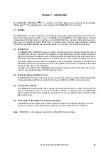
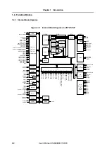
The CPU uses five-stage pipeline control to enable single-clock execution of address calculations,
arithmetic logic operations, data transfers, and almost all other instruction processing.
Other dedicated on-chip hardware, such as a multiplier (16 bits × 16 bits
→
32 bits
or 32 bits
×
32 bits
→
64 bits) and a barrel shifter (32 bits), help accelerate processing of complex
instructions.
(2)
Bus control unit (BCU)
The BCU starts the required external bus cycle based on the physical address obtained by the
CPU. When an instruction is fetched from external memory area and the CPU does not send a bus
cycle start request, the BCU generates a prefetch address and prefetches the instruction code.
The prefetched instruction code is stored in an instruction queue in the CPU.
The BCU controls a memory controller (MEMC) and DMA controller (DMAC) and performs
external memory access and DMA transfer.
(a) Memory controller (MEMC)
Note2
The MEMC controls SRAM, ROM, and various I/O for external memory expansion.
•
SRAM, external ROM, external I/O interface
Supports access to SRAM, external ROM, and external I/O.
(b) DMA controller (DMAC)
The DMAC performs data transfers b/w internal on-chip RAM and peripheral I/O. For this purpose
eight DMA channels are provided for particular transfer functions of serial I/O interfaces, real-time
pulse unit (TMR), and A/D converter.
(3)
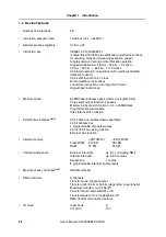
ROM
There is on-chip flash memory of 512 KB provided in the
μ
PD70F3187, and 384 KB in the
μ
PD70F3447.
On an instruction fetch, the ROM can be accessed by the CPU in one clock.
When single-chip mode 0 or flash memory programming mode is set, ROM is mapped starting
from address 00000000H.
When single-chip mode 1
Note2
is set, it is mapped starting from address 00100000H.
ROM cannot be accessed if ROM-less mode
Note2
is set.
(4)
RAM
There is on-chip RAM of 32 KB provided in the
μ
PD70F3187, and 24 KB in the
μ
PD70F3447. On-
chip RAM is mapped starting from address 03FF0000H for both,
μ
PD70F3187 and
μ
PD70F3447.
It can be accessed by the CPU in one clock on an instruction fetch or data access.
(5)
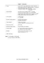
Interrupt controller (INTC)
The INTC services hardware interrupt requests from on-chip peripheral I/O and external sources
(NMI, INTP0 to INTP12). Eight levels of interrupt priorities can be specified for these interrupt
requests, and multiple-interrupt servicing control can be performed for interrupt sources
Содержание V850E/PH2
Страница 6: ...6 Preface User s Manual U16580EE3V1UD00...
Страница 16: ...16 User s Manual U16580EE3V1UD00...
Страница 28: ...28 User s Manual U16580EE3V1UD00...
Страница 32: ...32 User s Manual U16580EE3V1UD00...
Страница 84: ...84 Chapter 2 Pin Functions User s Manual U16580EE3V1UD00 MEMO...
Страница 144: ...144 Chapter 3 CPU Functions User s Manual U16580EE3V1UD00 MEMO...
Страница 192: ...192 Chapter 5 Memory Access Control Function PD70F3187 only User s Manual U16580EE3V1UD00 MEMO...
Страница 312: ...312 Chapter 9 16 Bit Timer Event Counter P User s Manual U16580EE3V1UD00 MEMO...
Страница 534: ...534 Chapter 11 16 bit Timer Event Counter T User s Manual U16580EE3V1UD00...
Страница 969: ...969 Chapter 20 Port Functions User s Manual U16580EE3V1UD00 MEMO...
Страница 970: ...970 Chapter 20 Port Functions User s Manual U16580EE3V1UD00...
Страница 976: ...976 Chapter 22 Internal RAM Parity Check Function User s Manual U16580EE3V1UD00 MEMO...
Страница 984: ...984 Chapter 23 On Chip Debug Function OCD User s Manual U16580EE3V1UD00 MEMO...
Страница 1006: ...1006 Chapter 24 Flash Memory User s Manual U16580EE3V1UD00 MEMO...
Страница 1036: ...1036 Chapter 27 Recommended Soldering Conditions User s Manual U16580EE3V1UD00 MEMO...
Страница 1046: ...1046 Appendix A Index User s Manual U16580EE3V1UD00 MEMO...
Страница 1052: ...1052 User s Manual U16580EE3V1UD00...
Страница 1053: ......


