


388
Chapter 10
16-bit Inverter Timer/Counter R
User’s Manual U16580EE3V1UD00
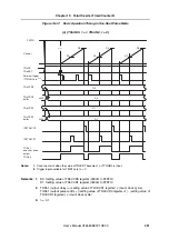
10.10.2 External event count mode
(1)
Outline of external event count mode
In the external event count mode, count up starts upon external event input (TEVTRn pin). (The
external event input (TEVTRn) is used as the count clock, regardless of bit TRnEEE of the
TRnCTL1 register.)
In the external event count mode, the counter is cleared only upon a match between the counter
and the value of the TRnCCR0 register. Counter clearing using the TRnCCR1 to TRnCCR5
registers is not performed.
However, the values of the TRnCCR1 to TRnCCR5 registers are transferred to the TRnCCR1 to
TRnCCR5 buffer registers, compared to the counter value, and compare match interrupts
(INTTRnCC1to INTRnCCR5) are output.
The TRnCCR0 to TRnCCR5 registers can be rewritten with the anytime write method, regardless
of the value of bit TRnCE.
Pins TORn1 to TORn7 are toggle output controlled when bits TRnOE1 to TRnOE7 are set to 1.
When a compare register TRnCCR0 to TRnCCR5 is not used, it is recommended to set it contents
to FFFFH.
[External event count operation flow]
<1> TRnCTL1 register bits TRnMD3 to TRnMD0 = 0001B (mode setting)
Edge detection set with TRnIOC2 register bits TRnEES1 and TRnEES0 (TRnEES1,
TRnEES0 = setting other than 00B)
<2> TRnCTL0 register bit TRnCE = 1 (count enable)
<3> TEVTRn pin input edge detection (count-up start)
Cautions: 1. In case of the external event count mode, when the content of the TRnCCR0
register is set to m, the number of TEVTRn pin input edge detection times is m+1.
2. Do not set the value of the TRnCCR0 register to 0000H in external event count
mode.
3. When a TRnCCR1 to TRnCCR5 register value is set to 0000H in external event
count mode the corresponding interrupt (INTTRnCC1 to INTTRnCC5) does not
occur immediately after start, but after the first overflow of the timer (FFFFH to
0000H).
4. TORn0 pin output cannot be used in external event count mode. Alternatively use
the interval timer mode (refer to section 10.10.1 “Interval timer mode” on
page 384) and set TPnEEE = 1 in conjunction with TOPn0 pin output.
Remark:
n = 0, 1
Содержание V850E/PH2
Страница 6: ...6 Preface User s Manual U16580EE3V1UD00...
Страница 16: ...16 User s Manual U16580EE3V1UD00...
Страница 28: ...28 User s Manual U16580EE3V1UD00...
Страница 32: ...32 User s Manual U16580EE3V1UD00...
Страница 84: ...84 Chapter 2 Pin Functions User s Manual U16580EE3V1UD00 MEMO...
Страница 144: ...144 Chapter 3 CPU Functions User s Manual U16580EE3V1UD00 MEMO...
Страница 192: ...192 Chapter 5 Memory Access Control Function PD70F3187 only User s Manual U16580EE3V1UD00 MEMO...
Страница 312: ...312 Chapter 9 16 Bit Timer Event Counter P User s Manual U16580EE3V1UD00 MEMO...
Страница 534: ...534 Chapter 11 16 bit Timer Event Counter T User s Manual U16580EE3V1UD00...
Страница 969: ...969 Chapter 20 Port Functions User s Manual U16580EE3V1UD00 MEMO...
Страница 970: ...970 Chapter 20 Port Functions User s Manual U16580EE3V1UD00...
Страница 976: ...976 Chapter 22 Internal RAM Parity Check Function User s Manual U16580EE3V1UD00 MEMO...
Страница 984: ...984 Chapter 23 On Chip Debug Function OCD User s Manual U16580EE3V1UD00 MEMO...
Страница 1006: ...1006 Chapter 24 Flash Memory User s Manual U16580EE3V1UD00 MEMO...
Страница 1036: ...1036 Chapter 27 Recommended Soldering Conditions User s Manual U16580EE3V1UD00 MEMO...
Страница 1046: ...1046 Appendix A Index User s Manual U16580EE3V1UD00 MEMO...
Страница 1052: ...1052 User s Manual U16580EE3V1UD00...
Страница 1053: ......


