background image

General Description  2-33 

Use of CD-ROM 

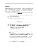
Observe the following when you use a CD-ROM on NEC Express5800/ft series: 


As for a disk such as a noncompliant “copy-protected CD,” we shall not guarantee that 
you can use a CD player to play it with this server. 


Be careful not to drop the CD-ROM. 


Do not bend or place anything on the CD-ROM. 


Do not attach labels on the CD-ROM. 


Do not touch the signal side (blank side). 


Place the CD-ROM gently on the tray with the printed side up. 


Do not scratch, or use a pencil or ballpoint pen to write on the CD-ROM. 


Keep away from cigarette smoke. 


Do not leave the CD-ROM in a place that is subject to direct sunlight or high temperatures 
(e.g., due to a heater). 


If the CD-ROM gets dirty with dust or fingerprints, wipe it gently from its center to edge 
with a dry soft cloth. 


When you clean the CD-ROM, use a CD cleaner.    Do not use a record cleaner (spray), 
benzine, or thinner. 


Store the CD-ROM in a protective case when not in use. 


Содержание Express5800/320Lb FT Linux

Страница 1: ...N8800 027F 028F NEC Express5800 320Lb 320Lb R User s Guide 1st Edition 02 2003 856 122693 901 A ...

Страница 2: ... Warranty Statement accompanying each product However actual performance of each such product is dependent upon factors such as system configuration customer data and operator control Since implementation by customers of each product may vary the suitability of specific product configurations and applications must be determined by the customer and is not warranted by NEC To allow for design and sp...

Страница 3: ... assets This guide uses the following three types of symbols to give indications and precautions against a danger They are defined as follows Indicates that a failure to follow the instructions could cause a danger Each image symbolizes a particular type of danger Attention Indicates what you must not do Each image symbolizes a particular type of prohibition Prohibited actions Indicates what you m...

Страница 4: ...a risk of losing eyesight due to laser beam Indicates a risk of an injury or damage to physical assets due to a hazardous material Prohibited actions Indicates a general prohibition that is not defined herein Do not disassemble repair or modify the equipment Otherwise there is a risk of an electric shock or fire Mandatory actions Unplug the server Otherwise there is a risk of an electric shock or ...

Страница 5: ... A digital apparatus meets all requirements of the Canadian Interference Causing Equipment Regulations Cet appareil numériqeu de la classe A respecte toutes les exigences du Règlement sur le matériel brouilleur du Canada CE Statement Warning This is a Class A product In residential environment this product may cause radio interference in which case the user may be required to take adequate measure...

Страница 6: ...ic and its logo are trademarks of QLogic Corporation in the United States Fast UTIL is a trademark of QLogic Corporation in the United States All other product brand or trade names used in this publication are the trademarks or registered trademarks of their respective trademark owners Microsoft Windows 2000 Server operating system Microsoft Windows 2000 Advanced Server operating system and Micros...

Страница 7: ... manual regardless of 4 above PREFACE Welcome to the NEC Express5800 ft series NEC Express5800 ft series is a fault tolerant ft server focusing on high reliability in terms of fault tolerance in addition to high performance scalability and general versatility provided by NEC Express5800 series In the event of trouble its dual configuration will allow the system to instantaneously isolate the faile...

Страница 8: ...out the product its component names functions operating procedures as well as handling of devices and other parts Chapter 3 Setup This chapter walks you through the setup procedures from unpacking of the product See also this chapter when you perform a re setup Chapter 4 System Configuration This chapter describes how to make settings of built in basic input output system It also describes factory...

Страница 9: ... and check the individual items If some component is missing or damaged contact your sales agent Keep the accessories in a safe place You will need them when you perform setup addition of options or replacement of failed components To check NEC EXPRESSBUILDER components see the attached list Be sure to fill out and mail the software registration card that is attached to your operating system Make ...

Страница 10: ...iv This page is intentionally left blank ...

Страница 11: ...Proper Operation 1 15 Transfer to Third Party 1 16 Disposal of Equipment and Consumables 1 17 If System Trouble is Suspected 1 18 About Our Web Service 1 18 Chapter 2 General Description 2 1 Standard Features 2 2 Names and Functions of Components 2 6 Front View 2 6 Front View inside 2 8 CD ROM Drive 2 9 Rear View 2 10 CPU Module 2 12 PCI Module 2 14 Chassis Board Layout 2 15 LEDs 2 16 Basic Operat...

Страница 12: ...3 45 Global Array Manager 3 45 Backup of System Information 3 46 Setting Up the Optional Boards 3 46 Confirmation of the ft Control Software Version 3 47 Chapter 4 System Configuration 4 1 System BIOS SETUP 4 2 Starting SETUP Utility 4 3 Description on On Screen Items and Key Usage 4 4 Configuration Examples 4 5 Menu and Parameter Descriptions 4 8 SCSI BIOS Fast UTIL 4 28 Start 4 28 Configuration ...

Страница 13: ...8 Configuration 5 89 Remote Console Connection When No Console is Hooked Up 5 89 VERITAS Volume Manager 5 94 Installing Volume Manager 2 7 for Windows 2000 5 94 Hard Disk Configurations 5 114 ftMemory RAM Disk 5 118 Chapter 6 Maintenance 6 1 Daily Maintenance 6 2 Checking Alert 6 2 Checking STATUS LEDs and LCD Display 6 2 Making Backup Copies 6 3 Cleaning 6 3 System Diagnostics 6 7 Test Items 6 7 ...

Страница 14: ...Management Application Error Messages 7 23 Solving Problems 7 24 Problems with NEC Express5800 ft series 7 24 Problems with NEC EXPRESSBUILDER 7 32 Problems with NEC Express5800 ft series Setup 7 33 Problems with Master Control Menu 7 33 Problems with NEC ESMPRO 7 34 Collection of Trouble Logs 7 35 Collection of Event Logs 7 35 Collection of Configuration Information 7 36 Collection of Diagnostic ...

Страница 15: ...ule 8 31 Removing CPU Module 8 32 Installing CPU Module 8 35 DIMM 8 38 Installing DIMM 8 40 Removing DIMM 8 42 Replacing DIMM 8 43 Processor CPU 8 44 Installation 8 45 Removing CPU 8 48 Replacing CPU 8 49 PCI Module 8 50 Precautions 8 51 Removing PCI Module 8 52 Installing PCI Module 8 55 PCI Board 8 58 Installing PCI Board 8 59 Removing PCI Board 8 64 Replacing PCI Board 8 65 Setup of Optional PC...

Страница 16: ...x This page is intentionally left blank ...
Страница 17: ...Chapter 1 Precautions for Use This chapter includes information necessary for proper and safe operation of the server ...

Страница 18: ...at the user stays alert to possible risks Do not remove or damage these labels If some label is missing about to peel off or illegible contact your sales agent The figures below show locations of the labels on tower model and rack mount model servers Tower model Label E Label A Label D Label B Label C ...

Страница 19: ...Precautions for Use 1 3 Label A Label B Label C Label E Label D ...

Страница 20: ...1 4 Precautions for Use Rack mount model Label B Label A Label C Label D ...

Страница 21: ...Precautions for Use 1 5 Label D Label C Label B Label A ...

Страница 22: ...1 6 Precautions for Use PCI CPU Modules PCI Module CPU Module Label A Label A Label A ...

Страница 23: ...detect smoke odor or noise If the equipment emits smoke odor or noise immediately flip off the POWER switch unplug the cord and contact your sales agent There is a risk of a fire Do not insert a wire or metal object Do not insert a wire or metal objects into a vent or disk drive slot There is a risk of an electric shock Do not use the equipment in an unsuitable place Do not install a server rack i...

Страница 24: ...tally enter the equipment immediately turn off the power and unplug the cord Contact your sales agent instead of trying to disassemble it yourself Do not touch any damaged LCD The LCD on the server front contains a liquid harmful to the human body If the liquid leaked from the LCD accidentally gets in your mouth immediately gargle and see a doctor If it accidentally gets on your skin or in your ey...

Страница 25: ...e rated current is exceeded there is a risk of overheating that could lead to a fire Do not plug the cord insecurely Insert the plug firmly into an outlet Otherwise there is a risk of heat or fire due to poor contact If dust settles on the slots and it absorbs moisture there is also a risk of heat or fire Do not use nonconforming power cords Use only the power cords that come with the product If t...

Страница 26: ...nfiguration If you carry it alone you may strain your back It takes at least four people to carry it hold the equipment firmly by its bottom Do not hold the front bezel or it may become detached causing an injury Do not install the equipment in an unsuitable place Install the equipment in such a place as specified in this User s Guide Avoid the following or there is a risk of a fire a dusty place ...

Страница 27: ...an internal device cable or connector may cause an electric shock or a fire resulted from a short circuit Do not use any non designated interface cable Use only interface cables designated by NEC identify which component or connector to attach beforehand If you use a wrong cable or make a wrong connection there is a risk of short circuit that could lead to a fire You also have to observe the follo...

Страница 28: ...of disassembling replacing or recharging it yourself Disconnect the power plug before cleaning the server Make sure to power off the server and disconnect the power plug from a power outlet before cleaning or installing removing internal optional devices Touching any internal device of the server with its power cord connected to a power source may cause an electric shock even of the server is off ...

Страница 29: ...nder before you unplug the equipment do not touch the equipment and cables There is a risk of a fire or electric shock Keep animals away Animal s waste or hair may get inside the equipment to cause a fire or electric shock Do not place any object on top of the server The server may fall down to cause damage to physical assets Do not leave the CD tray ejected Dust may get in the equipment to cause ...

Страница 30: ...eight attach stabilizers or install two or more racks Otherwise it may fall down to cause injuries Do not assemble parts alone It takes at least two people to mount doors and trays to a rack Otherwise you may drop some parts to cause a breakage or injuries Do not pull a device out of the rack if it is unstable Before pulling out a device make sure that the rack is fixed by stabilizers or quake res...

Страница 31: ...roduction of copy protect CDs using reproduction equipment if such disks do not comply with CD standards Clean the equipment regularly For procedures see Chapter 6 Regular cleaning is effective in preventing various types of trouble Lightning may cause voltage sag As a preventive measure it is recommended to use UPS uninterruptible power supply This equipment does not support the connection throug...

Страница 32: ...at command to erase data superficially the data actually remains on the hard disk If data is not erased completely it could be restored by certain software and be used for unexpected purposes You are strongly recommended to buy a special type of software or service to avoid such trouble For details contact your sales agent NEC shall not be accountable for such data leakage caused by your failure t...

Страница 33: ...o protect privacy and confidential information Some of the system components have limited lifetime e g cooling fans built in batteries built in CD ROM drive floppy disk drive mouse For stable operation it is recommended to replace them regularly For lifetime of individual components and replacing procedures ask your sales agent WARNING Do not detach a lithium battery yourself This equipment has a ...

Страница 34: ...s Check if these programs are properly installed 4 Use a commercially available anti virus program to check the server If the problem isn t solved by the above actions stop using the server and consult with your sales agent In this case check LED indications of the server and alarm indications on the display which will serve as helpful information at the time of repair ABOUT OUR WEB SERVICE Inform...

Страница 35: ...justment it is difficult to maintain a good work posture and may get tired soon Be sure to adjust the angle before using the display Adjust Brightness and Contrast Displays allow you to adjust brightness and contrast Optimum brightness and contrast vary depending on the individual age brightness of the room etc you need to make an adjustment accordingly If the screen is too bright or too dark it i...

Страница 36: ...1 20 Precautions for Use This page is intentionally left blank ...

Страница 37: ...hapter 2 General Description This chapter describes what you need to know to use the NEC Express5800 ft series Refer to this chapter when you want to know about certain components and how to operate them ...

Страница 38: ...toring feature 1 bit error correction 2 bit error detection Bus parity error detection Temperature monitoring Error notification Built in fan monitoring feature Internal voltage monitoring feature BIOS password feature Security feature security lock for front door and front bezel Power On Self Test POST Test and Diagnosis T D Utility Management Utilities Maintainability NEC ESMPRO NEC Management W...

Страница 39: ...g and redundant memory It assures data redundancy through duplication of server data on an independent storage system These features eliminate server downtime that is usually caused by network disconnection or trouble with the I O controller Ethernet adapter or disk drive and support operation of the network and server applications continuously While being transparent to application software NEC E...

Страница 40: ...pplications You can run Windows 2000 compliant applications on NEC Express5800 ft series Thus unlike other highly fault tolerant products special API or scripts are not necessary Automatic mirroring NEC Express5800 ft series automatically maintains data as the current data You need to make a setting with VERITAS Volume Manager Automatic detection and notification of faults NEC Express5800 ft serie...

Страница 41: ...NT or Windows 95 98 Me Event notification function When trouble or other events are detected on NEC Express5800 ft series they will be notified to Windows 2000 Event Log and saved Therefore you can view the log items locally or remotely by a usual Windows 2000 procedure Since an NEC Express5800 ft series events use unique IDs they are easy to distinguish In service repairing You can repair or repl...

Страница 42: ...2 6 General Description NAMES AND FUNCTIONS OF COMPONENTS Names and functions of components are shown below Front View Tower model Rack mount model ...

Страница 43: ...ing a tower model unit 4 Casters Wheels for moving a tower model unit 5 BMC status LED See LEDs in this chapter for details 6 PCI module status LED 1 See LEDs in this chapter for details 7 PCI module status LED 2 See LEDs in this chapter for details 8 DISK ACCESS LED See LEDs in this chapter for details 9 CPU module status LED 1 See LEDs in this chapter for details 10 CPU module status LED 2 See L...

Страница 44: ...2 8 General Description Front View inside Tower model Rack mount model ...

Страница 45: ...o assume primary functionality 6 CD ROM drive Used for reading data from CD ROMs Although there are two CD ROM drives only the one on the active primary PCI module can be used the module with the lit POWER Switch LED 7 3 5 inch disk bay Slots for adding hard disks On a tower model they are called Slots 1 2 and 3 from the bottom On a rack mount model they are called Slots 1 2 and 3 from the left Sl...

Страница 46: ...ption Rear View Rack mount model Tower model PCI module for Group1 PCI module for Group2 CPU module for Group1 CPU module for Group2 CPU module for Group1 CPU module for Group2 PCI module for Group2 PCI module for Group1 ...

Страница 47: ... SCSI devices 8 PCI module status LED 1 See LEDs in this chapter for details 9 PCI module status LED 2 See LEDs in this chapter for details 10 PCI board slot status LED Slot1 See LEDs in this chapter for details 11 PCI board slot status LED Slot2 See LEDs in this chapter for details 12 PCI board slot status LED Slot3 See LEDs in this chapter for details 13 LINK ACT LED See LEDs in this chapter for...

Страница 48: ...oup 1 and group 2 have the same configuration 1 Module handle 2 Cooling fan 3 CPU module board 4 CPU socket 2 additional 5 AC inlet in the back 6 Backboard connector in the back 7 CPU socket 1 standard 8 DIMM 9 Power unit 10 Power backboard ...

Страница 49: ...fan connector 2 LED connector 3 Power connector 4 CPU socket 2 5 CPU socket 1 6 DIMM sockets Slots 1 to 6 from left Add memory modules in pairs 1 and 2 3 and 4 5 and 6 This section only describes connectors that are used for replacing parts or upgrading Other connectors have been setup before shipment ...

Страница 50: ...n PCI Module Group 1 and group 2 have the same configuration 1 Cooling fan 2 Power unit 3 AC inlet in the rear 4 Backboard connector in the rear 5 PCI module board 6 Video board 7 PCI riser card 8 PCI board retention bracket ...

Страница 51: ...ion 1 SCSI connector external 2 Configuration jumper pin 3 Battery lithium battery 4 Cooling fan 1 connector 5 Power connector 6 IDE connector 7 Power switch connector 8 9 LED connector SCSI connector internal Chassis Board Layout Rack mount model 8 Clock board Interface board Back panel ...

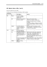
Страница 52: ... use the NEC ESMPRO or the Off line Maintenance Utility to view the error log When you want to restart the server perform a shutdown if the OS allows you to shut down the system If not perform a reset or forced shutdown or you can restart the server by unplug and plugging the power cord LED indications Description Action Green BMC operates normally and CPU and PCI modules are in duplex mode Green ...

Страница 53: ...nd Detected a fan alarm If LCD displays some error message refer to the error message list see Chapter 7 Check if dust is accumulated on internal fans and confirm that the fan cables are connected firmly If the message does not disappear contact your sales agent BMC is being dumped Wait for a while it will go off soon PCI module may be connected incorrectly Check if PCI module is connected correct...

Страница 54: ...es agent Off Off AC power is not supplied to the PCI modules Remount the PCI module Check the condition of power unit Check if the power cord is connected correctly Check the condition of breaker and UPS If the problem persists contact your sales agent Status LEDs and Disk Access LED stay amber on both PCI modules they are shifting to duplex mode by mirroring Wait until the mirroring is finished O...

Страница 55: ...r The CPU module is mounted correctly and operates in simplex mode Start the other CPU module to use ft series features If the problem persists contact your sales agent Green The CPU module is performing diagnosis On standby AC power is supplied through the cord but the system has not been powered on yet After turning on the power wait for the OS to start When the OS starts and duplex mode is esta...

Страница 56: ...odule correctly If the problem persists contact your sales agent For LED indications when option boards are attached see PCI Module in Chapter 8 Hard Disk LED A hard disk LED shows the status of hard disks that are mounted in the 3 5 inch device bay Combined the two hard disk LEDs on PCI modules 1 and 2 show the status of the hard disks PCI module 1 PCI module 2 Description Action Green Green Hard...

Страница 57: ... Operating as 1000BASE T Off Operating as 10BASE T Operating as 10BASE T LINK ACT LED The LINK ACT LED shows the status of a standard network port It is green if power is supplied to the main unit and hub and they are connected correctly LINK It blinks green while the network port sends or receives data ACT When the LED does not illuminate during LINK check the condition and connection of network ...

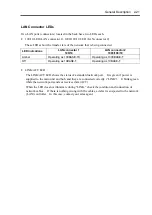
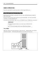
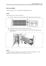
Страница 58: ...e detached The rack mount model server has a cover like detachable bezel You need to open the front bezel when you access the POWER switch CD ROM drive or hard disk IMPORTANT Without using the security key you cannot open or detach the front bezel It is not recommended to use the server with its bezel detached Tower Model Insert the security key into the slot and turn it to release the lock Hold t...

Страница 59: ...it with a little pressure to release the lock 2 Hold the right side of the front bezel lightly and pull it open 3 Detach the bezel from the main unit by sliding it to the left a little to disengage the tabs from the frame Attach To attach the front bezel engage the tabs on the frame on the left side of the main unit After attaching and closing the front bezel lock it with the key for security Tabs...

Страница 60: ... it is powered on 2 Open the front bezel or detach it in the case of a rack mount model 3 Press the POWER switch located on the front panel After a while the NEC logo will appear on the screen IMPORTANT Do not turn off the power before the NEC logo appears While the NEC logo is displayed on the screen NEC Express5800 ft series is performing a power on self test POST to check itself For details see...

Страница 61: ...xpress5800 ft series is plugged to a UPS see manuals included with the UPS or the application that controls the UPS 1 Perform a normal shutdown from Windows 2000 Advanced Server The system will be powered off automatically and the POWER LED will turn off 2 Power off all peripheral devices ...

Страница 62: ... s details press Esc Tips You can view POST details from the beginning without the need to press Esc when the BIOS menu is displayed select System Configuration Advanced and set Boot time Diagnostic Screen to Enabled see Chapter 4 You can view the test items and details from a management PC where NEC ESMPRO Manager or MWA is installed You don t always need to check POST details You will need to ch...

Страница 63: ... message appears together with an error message you don t need to start the utility to modify the configuration If you wait for a few seconds POST will go on automatically To start the SETUP utility press F2 while the above message is displayed For setting and parameter functions see the section of BIOS setup When SETUP is completed the server will reboot itself automatically and perform POST 5 A ...

Страница 64: ...n this manner the server retries POST or OS startup with different combinations of CPU PCI modules If POST does not finish normally with any combinations the server will stop with the state of DC OFF Press F1 to resume F2 to enter SETUP While performing retries the server displays or registers the error types For details of error messages see Chapter 7 Troubleshooting POST Error Messages When the ...

Страница 65: ...ing Windows 2000 operating system boot up B will be assigned to the floppy disk drive for the standby PCI module Only the floppy disk drive of the primary PCI module will be recognized by the Windows 2000 operating system The floppy disk drive of the secondary PCI module will not be recognized Only one floppy disk drive is recognized at any given time Ex Primary PCI module connects the floppy disk...

Страница 66: ...n unformatted disk you will see a message that the disk cannot be read or that needs formatting To format a floppy disk see your OS manual If you power on or restart NEC Express5800 ft series with a floppy disk left in the drive the server will access the floppy disk to start the system Unless a system exits on the FD the server will be unable to start To remove a floppy disk from the drive press ...

Страница 67: ...ic objects Do not clip disks Be careful not to drop Store floppy disks in a protective case where they are kept away from magnetic waves or dust To prevent data from being erased accidentally the floppy disk has a write protect notch When the disk is write protected you can read data but you cannot write the data or format the disk It is recommendable to write protect floppy disks that contain imp...

Страница 68: ...ted When you cannot eject a CD ROM When you cannot eject the CD ROM by pressing the eject button follow the steps below to eject it 1 Press the POWER switch to power off the server 2 Use a metal pin of about 1 2 mm in diameter and 100 mm long alternatively you can use a fairly large paper clip after straightening Insert it gently into the manual release hole located to the right of the eject butto...

Страница 69: ...touch the signal side blank side Place the CD ROM gently on the tray with the printed side up Do not scratch or use a pencil or ballpoint pen to write on the CD ROM Keep away from cigarette smoke Do not leave the CD ROM in a place that is subject to direct sunlight or high temperatures e g due to a heater If the CD ROM gets dirty with dust or fingerprints wipe it gently from its center to edge wit...

Страница 70: ...2 34 General Description This page is intentionally left blank ...
Страница 71: ...Chapter 3 Setup This chapter describes setup procedures to make NEC Express5800 ft series ready for use ...

Страница 72: ...ional PCI boards after the setup of the operating system is completed 2 Install NEC Express5800 ft series in a most suitable place environment 3 Connect the display unit external USB FDD mouse and keyboard to the server IMPORTANT Connect peripherals such as external backup device to the server after the setup of the operating system is completed 4 Connect the accessory power cord to the receptacle...

Страница 73: ...ripherals and PCI card with cables 4 With the attached power cord connect the server to an AC outlet 5 Change the BIOS settings depending on the configuration of the server and system uses See the sample setup shown in Chapter 4 IMPORTANT Set BIOS correctly depending on your environment Make sure that the date and time are set correctly Setup of Windows 2000 Advanced Server After completing hardwa...

Страница 74: ...n a safe place You will need them when you perform setup addition of options or replacement of failed components To check NEC EXPRESSBUILDER components see the attached list Always mail the software registration card attached to the operating system after filling the proper information in the card Make backup copies of included floppy disks if any Keep the original disks as the master disks use th...

Страница 75: ...places It is recommendable to use the server in a room where temperature can be kept between 15 and 25ºC 100V 120 V or 200V 240 V parallel bi polar power outlet with grounding Room that can maintain the following conditions during operation Temperature 10 to 35ºC Humidity 20 to 80 non condensing Wall outlet within the reach of supplied power cord UPS to prevent momentary voltage drop due to power ...

Страница 76: ...ications antenna power transmission wire and electromagnetic crane If unavoidable contact your sales agent to request proper shield construction Place where the power cord of the server must be connected to an AC outlet that shares the outlet of another device with large power consumption Place that is close to some equipment that causes power noises e g sparks caused by power on off using a relay...

Страница 77: ...llow the procedures below to install the CPU and PCI modules Note the followings before installing them Confirm the main cabinet is immobilized Place removed modules to the side of the system Do not place modules on top of the system It takes at least two people to mount the modules mount them slowly and carefully If you cannot install modules smoothly remove them and try again Install the CPU mod...

Страница 78: ... not attempt to install the server into the rack assembly The server should be installed in the rack only by trained maintenance personnel It is recommened to use the server in a room where temperature can be kept between 15 and 25ºC Wall outlet within the reach of supplied power cord 100V 120 V or 200V 240 V parallel bi polar power outlet with grounding Space 40 cm or more on top 1 m or more on t...

Страница 79: ...n such places as listed below Otherwise the server may malfunction Place where you cannot pull out the components fully Place that cannot sustain the total weight of the rack system Place where you cannot mount stabilizers or where you cannot perform installation without quake resistant engineering Place whose floor is uneven or inclined Place where temperatures change widely near a heater air con...

Страница 80: ...on IMPORTANT Temperature increase inside the rack and airflow If you install several components or the ventilation isn t good inside the rack the internal temperature may increase due to heat emitted from the components When the operating temperatures of NEC Express5800 ft series 10 to 35 C are exceeded there is a risk of malfunction You must take adequate precautions and measures for airflow insi...

Страница 81: ...the following instructions to use the equipment safely Failure to follow these instructions may cause a burn personal injury or damage to physical assets For details see safety precautions in Chapter 1 Do not plug the power cord in a nonconforming outlet Do not plug too many cords in a single outlet Do not plug the cord insecurely Do not use nonconforming power cords IMPORTANT Power off the server...

Страница 82: ...PORTANT Connection of optional devices In the case of standard configuration you need to complete setup of the operating system before mounting optional PCI cards or hard disks that you bought separately In the case of Build to Order configurations if N8803 030 or 031 is mounted be sure to connect cables to the additional cabinets before going on to the next steps Display To a 100Mbps network To a...

Страница 83: ...ill become the primary module The power connector A is used for Group 1 the power connector B is for Group 2 The module whose POWER switch LED is on is the primary To connect the power cord from the server to an uninterruptible power supply UPS use service outlets on the rear of the UPS The UPS service outlets are categorized into two groups SWITCH OUT and UN SWITCH OUT They may be called OUTPUT1 ...

Страница 84: ...3 14 Setup Select System Hardware AC LINK on the BIOS setup utility and change parameters See Chapter 4 for details Example ...

Страница 85: ...rver is used to run the ft series Setup program You will also use the ft series Setup when you reinstall the operating system IMPORTANT If your computers have Windows 2000 Windows NT or Windows 95 98 Me that communicate with the NEC Express5800 ft series through TCP IP protocol make the following settings for each computer 1 Copy WINNT W2K FTREG EXE from the NEC EXPRESSBUILDER CD ROM into an arbit...

Страница 86: ...lues TcpMaxConnectRetransmissions Type REG_DWORD Set value 5 Values TcpMaxDataRetransmissions Type REG_DWORD Set value 8 Values TcpMaxConnectREsponseRetransmissions Type REG_DWORD Set value 5 Windows 95 98 Me Registry key HKEY_LOCAL_MACHINE SYSTEM CurrentControlSet Services VxD MSTCP Values MaxConnectRetries Type String Set value 5 Values MaxDataRetries Type String Set value 8 ...

Страница 87: ...tup 3 17 Setup Flow Follow the flowchart below to setup the server See also this section when re installing the system START ft series Setup Setup for Failure Management System Data Backup Setup Completed ...

Страница 88: ...m for the first installation and reinstallation of the operating system This program accomplishes complicate setups Before performing ft Series Setup contact your sales agent about the latest release of ft control software Operating System Installation Read the notes here carefully before installing the operating system Operating System Supported by the NEC Express5800 ft series NEC Express5800 ft...

Страница 89: ... create mirrored volumes or disable delete them select Volume Manager for Windows from Computer Management Size of the Partition to be Created The required minimum size of a partition to install the system can be obtained from the following formula 2048MB paging file size dump file size 2048MB size required for installation Paging file size recommended size of memory mounted 1 5 Dump file size siz...

Страница 90: ...e of ft series setup you need to create a partition of 3072MB or more to perform auto installation About Auto Installation of Utilities The ft series setup installs the following utilities automatically NEC ESMPRO Agent VERITAS Volume Manager NEC ESMPRO report service for VERITAS Volume Manager ...

Страница 91: ...ws 2000 Specify the size of the partition to install the OS Insert Windows 2000 Advanced Server CD ROM Automatic installation starts Windows2000 Advanced Server ft control software NEC ESMPRO Agent VERITAS Volume Manager Windows2000 Setup Wizard starts Agree to the terms of software license Enter user name and company name Set dual LAN configuration Make setting of BIOS Run Setup from NEC EXPRESSB...

Страница 92: ...crosoft Windows 2000 Advanced Server CD ROM Windows 2000 Service Pack CD ROM User s Guide this manual IMPORTANT For the latest release of ft control software and purchase of the latest version of its Update CD ROM contact your sales agent 1 Turn on the peripheral equipment and then the NEC Express5800 ft series IMPORTANT You can mount only one disk into Slot 1 of the PCI module for Group 1 the PCI...

Страница 93: ... Ver n n UPDATE CD ROM change the CD in the drive to the UPDATE CD ROM and press any key If you do not have the UPDATE CD ROM press any keywithout changing the CD When the system files are copied the product ID input box appears 8 Enter the product ID of Windows 2000 Advanced Server The product ID of Windows 2000 Advanced Server is printed on the label of NEC Express5800 ft series 9 Specify the si...

Страница 94: ... is completed the Welcome to the Windows 2000 Setup Wizard screen appears 12 Click Next The License Agreement screen appears 13 Carefully read the terms of software license agreement and click Agree when you agree to the terms and then click Next If you do not agree to the terms click Disagree and then Next IMPORTANT If you do not agree to the terms of software license the ft series Setup program ...

Страница 95: ...e included NEC EXPRESSBUILDER CD ROM This pdf file is located in the following directory CD ROM VXVM VM Documentation You will find VERITAS Volume Manager s authentic license key in an ID label that is placed on NEC Express5800 ft series The license key does not use the following alphanumeric characters 1 5 and Q IMPORTANT Do not use VERITAS Volume Manager s dynamic relocation and hot spare functi...

Страница 96: ...ponents from Network Component Tree The pop up menu appears Select Create New Team Fault Tolerance IMPORTANT Do not select the command other than Fault Tolerance on the standard PCI module Team 1 Adaptive Fault Tolerance Mode is added to Network Component Tree 4 Select Stratus emb 10 100 Enet Adapter from Network Component Tree The pop up menu appears Select Add to Team Team 1 Adaptive Fault Toler...

Страница 97: ...ith Stratus emb 82544GC Copper Gigabit Adapter In Step 3 you can also select Load Balancing In this case Team X Adaptive Load Balancing Mode will be added 7 Click OK The Intel R PROSet II dialog box closes after a while and the settings become effective IMPORTANT Digital signature not found dialog box may appear several times If it appears click Yes After the settings of dual configuration Intel R...

Страница 98: ...ynamic disk set the disk for mirroring to the slot Do not set the disk to the slot before upgrading Set the mirroring for the disk with the same target ID See Hard Disk configurations that can be built by VxVM on the NEC Express5800 ft series in Chapter 5 for details 1 Select Start Setting Control Panel and then Control Panel screen appears 2 Double click Administration Tool double click Computer ...

Страница 99: ... which the system is installed and select New dynamic disk group A Dynamic Disk Group creation wizard will appear 6 Enter DynamicGroup in Group name and select the Create Windows2000 Disk Management compatible group check box 7 Check to see if the selected disk is the one where you installed the system and click Next 8 Check the list of disks you are going to upgrade and click Next ...

Страница 100: ...sted several times Always restart the machine after confirming the PCI module duplication When the machine is restarted before the PCI module duplication the dual LAN may become invalid If the dual LAN becomes invalid make the settings of dual Lan again Check the PCI module duplication as follows The PCI module duplication is valid if both the status LED of PCI module 1 and that of PCI module 2 ar...

Страница 101: ...n click Mirror Add to access the Add Mirror Wizard 15 When the Add Mirror wizard appears check Select disk manually select a disk to mirror and click Select 16 After checking the settings click OK TIPS To add mirror to the volume having 18 GB it will take about 37 minutes IMPORTANT If you reboot system while mirroring the volume mirroringwill not complete Until the mirroring is finished DO NOT reb...

Страница 102: ...ation manuals of the peripheral devices Set dual configurations after the LAN cards and hard disk drives are added See Setting Dual LAN Configuration and Mirroring the Volume with Volume Manager for Windows 2000 in Chapter 3 Changes to BIOS settings After completing the installation start the BIOS setup utility to set Boot Monitoring of Advanced Monitoring Configuration to Enable save the settings...

Страница 103: ... make settings of memory dump only Sometimes a message indicating a shortage of virtual memory appears at the system startup when a failure has occurred after making settings described here and you have restarted the system to save the memory dump Continue the startup If you restarting the system you may not be able to collect the memory dump accurately Take the following steps to set memory dump ...

Страница 104: ...2MB or more If the memory has been expanded the size of debug information memory dump to be collected changes Check the size of free space where debug information memory dump is to be written If memory of 2GB or more is mounted the dump file size can be up to 2048MB Free space of about 2048MB 12MB is required 6 Click Performance Options 7 Click Change in the Virtual Memory dialog box 8 Change the ...

Страница 105: ... if the memory dump can be collected in normally beforehand If the memory has been expanded re set the paging file according to the memory size 9 Click OK A message is displayed asking you to restart the system depending on the changed settings Restart the system according to the messages ...

Страница 106: ...ox appears 3 Specify where you want to save diagnostic information in the Log File Path box Diagnostic information is saved under the file name DRWTSN32 LOG NOTE Do not specify a network path Be sure to specify a path on the local computer 4 Specify the crash dump file save destination in the Crash Dump box TIPS A crash dump file is a binary file that can be read by Windows Debugger 5 Select the f...

Страница 107: ...s 3 Click Add Remove Windows Components The Windows Components Wizard dialog box appears 4 Select the Management and Monitoring Tools check box of components and click Next 5 If a message is displayed asking you to insert Windows 2000 Advanced Server or Service Pack 3 disk insert the Windows 2000 Advanced Server CD ROM into the CD ROM drive and click OK 6 Click Finish in the Windows Components Wiz...

Страница 108: ...rams in the listed order 1 VERITAS Volume Manager 2 VERITAS Enterprise Administrator Service 3 VERITAS Enterprise Administrator 3 Install the Terminal Services 4 Install VERITAS Volume Manager 5 Install the hotfix of VERITAS Volume Manager If there is no hotfix to apply skip 5 TIPS When the installation of terminal services is started the warning for the four applications appears as you see in the...

Страница 109: ...eed to use the system update function IMPORTANT After you implement the following procedure update a system Update the system after all the optional PCI boards are removed 1 Log on to the system with OS installed as user with Administrator authority IMPORTANT Check that the dual system is configured properly Check that STATUS2 LED of each PCI module stays green 2 Dual LAN is canceled IMPORTANT Whe...

Страница 110: ...eamed adapters constituting dual configuration is removed Click Yes button to remove the adapter from Team Remove the other adapter Stratus emb 82559 10 100 Enet Adapter and Stratus emb 82544GC Copper Gigabit Adapter in the same way d Right click Team 1 Adaptive Fault Tolerance Mode and select Remove At that time the dialog box shown on the right is displayed This is a message for confirmation so ...

Страница 111: ...the Control Panel dialog box will be displayed b Double click the Add Remove Programs icon on the Control Panel dialog box And then the Add Remove Programs dialog box will be displayed c Select Intel R PROSet II from a list of Currently installed programs d Click the Change Remove button At that time the message on dialog box will be displayed This is a message for confirmation of deletion so clic...

Страница 112: ...000 Service Pack 3 during the system update If you do not have an UPDATE CD ROM of NEC Express5800 ft series ft control software and use NEC EXPRESSBUILDER CD ROM a After logging in to the system as an account such as Administrator insert NEC EXPRESSBUILDER CD ROM into the drive b On the Master Controller Menu screen that appears click Software Setup and click System Update on the menu c Follow th...

Страница 113: ...m 4 Start Explorer from Program of Start menu 5 Overwrite the following files by copying them File names USBD SYS OPENHCI SYS From C PNPDRVRS To C Winnt system32 drivers Since the NEC Express5800 ft series module is replaced with the Service Pack module by applying Windows 2000 Service Pack 3 you will need to replace it with ft series module again After that check to see that the file version is 1...

Страница 114: ...es Setup program It has been installed on the hard disk of a pre installed model at shipment Click Start Programs and make sure that the installed utility folder exists If it has not bee installed while setting up the ft series see Chapter 5 and install it IMPORTANT Make sure that NEC ESMPRO Agent is installed because it is indispensable for continuous operation of NEC Express5800 ft series To set...

Страница 115: ...h a network The MWA provides management on the process from power on POST execution to OS boot up of the server Checking the BIOS setup of the NEC Express5800 ft series from the management PC Starting the server through the floppy disk in the floppy disk drive of the management PC To establish communication between the NEC Express5800 ft series and the management PC via a LAN WAN or serial port in...

Страница 116: ...nto the CD ROM drive of the server and restart the system NEC EXPRESSBUILDER is activated and the NEC EXPRESSBUILDER Top Menu is displayed 3 Select Tool Off line Maintenance Utility 4 Select Save System NVRAM ROM Data from System Information Management Follow the instructions you see on the screen SETTING UP THE OPTIONAL BOARDS If one or more optional boards for the NEC Express5800 ft series inclu...

Страница 117: ...eries A tool for checking the version is provided Confirm the version afollowing the steps below 1 Log in the system as an authorized Administrator 2 Insert the provided NEC EXPRESSBUILDER CD ROM in the CD ROM drive Use the NEC Express5800 ft series ft control software UPDATE CD ROM if it is available 3 Run the tool installed in the CD to check the version of ft control software Tool name ftVerChk...

Страница 118: ...3 48 Setup This page is intentionally left blank ...
Страница 119: ...tion This chapter describes Basic Input Output System BIOS configuration When you install the server for the first time or install remove optional devices thoroughly read this chapter for better understanding and correct setups ...

Страница 120: ...MPORTANT The SETUP utility is intended for system Administrator use only The SETUP utility allows you to set a password The server is provided with two levels of password Supervisor and User With the Supervisor password you can view and change all system parameters of the SETUP utility With the User password system parameters available for viewing and changing are limited Do not set any password b...

Страница 121: ... to resume F2 to SETUP Press F1 to resume F2 SETUP F12 Network Press F2 to start the SETUP utility and display its Main menu If you have previously set a password with the SETUP utility the password entry screen appears Enter the password Enter password Up to three password entries will be accepted If you fail to enter the password correctly for three consecutive times the server halts You can no ...

Страница 122: ...ights upon selection menu Online help window Indicates there are submenus Setup item menu ft Memory Cursor Selects an item on the screen The highlighted item is currently selected Cursor Selects the Main Advanced Security System Hardware Boot or Exit menu and Changes the value parameter of the selected item When a submenu option an option preceded by Æ is selected these keys are disabled Enter Pre...

Страница 123: ... LAN Select Advanced Advanced RomPilot Support Enabled Remote operation via direct connection using cross cable Select System Hardware Console Redirection Direct Remote operation via WAN Select System Hardware Console Redirection Modem UPS To link power supply with the UPS To power on the server when power is supplied from the UPS Select System Hardware AC LINK Power On To keep the server off powe...

Страница 124: ...k Unmasked Select Security Power Switch Mask Masked IMPORTANT Masking the POWER switch disables forced shutdown see Chapter 7 as well as power on off using the POWER switch External Devices To setup external devices Select Advanced Peripheral Configuration and setup each device Internal Devices To install the disk array controller board or graphic accelerator board Select Advanced Option ROM PCI S...

Страница 125: ... Select Advanced Advanced RomPilot Support Enabled Remote operation via WAN Select System Hardware Console Redirection and set each item Memory To check the installed memory DIMM status Select Advanced Memory Reconfiguration and check the status indications Saving the Configuration Data To save the BIOS configuration data Select Exit Save Changes Exit or Save Changes To discard changes to the BIOS...

Страница 126: ...each menu Main Start the SETUP utility to display the Main menu Phoenix BIOS Setup Utility Main Advanced Security System Hardware Boot Processor Type Processor Speed Cache RAM System Memory Extended Memory BIOS Version System Time System Date Language Primary Master Tab Shift Tab or Enter selects field Item Specific Help Exit Intel R Xeon TM processor 2 40 GHz 512KB 584KB 511MB REL 6 0 8 M 1 18 54...

Страница 127: ...nly System Memory 584KB Indicates the total size of the basic memory view only Extended Memory Extended memory size Indicates the total size of the extended memory view only BIOS Version Version of BIOS Indicates the version of the system BIOS view only System Time HH MM SS Specify the current time System Date MM DD YYYY Specify the current date Language English US Français Deutsch Italiano Españo...

Страница 128: ...ct Advanced options Item Specific Help Phoenix BIOS Setup Utility Main Advanced Security System Hardware Boot Exit F1 Help Change Values F9 Setup Defaults F10 Save Changes Exit Sub Menu Enter Select Esc Exit Select Item Select Menu There is no configurable items on the above Advanced menu screen Display each sub menu and make settings on the sub menu screen Select an option with the mark and press...

Страница 129: ...option is set to Enabled Boot time Diagnostic Screen is unconditionally set to Enabled Post Error Pause Enabled Disabled Specify whether to stop POST at the end of POST when an error occurs during POST Factory set NOTE RomPilot is a BIOS feature for communications with the NEC Management Workstation Application NEC MWA To use the MWA for management of the server select Enable for RomPilot Support ...

Страница 130: ...nformation xxxxxxxx xxxxxxxx Phoenix BIOS Setup Utility Advanced F1 Help Change Values F9 Setup Defaults F10 Save Changes Exit Sub Menu Enter Select Esc Exit Select Item Select Menu See the table below for setup options on the screen Option Parameter Description Your Setting Processor 1 Type Processor 2 Type Indicates processor type installed on Processor 1 or Processor 2 view only Factory set ...

Страница 131: ...e below for setup options on the screen Option Parameter Description Your Setting DIMM 1 6 Size Indicates the size of memory installed on DIMMs 1 1 to 6 6 None indicates no DIMM installed view only DIMM 1 6 Speed Indicates the type of DIMM DDR200 DDR266 installed on DIMMs 1 0 to 6 6 None indicates no DIMM installed view only Factory set ...

Страница 132: ...Q 3 3F8 IRQ 4 1 2F8 IRQ 3 2 2F8 IRQ 4 3E8 IRQ 3 3E8 IRQ 4 2E8 IRQ 3 2E8 IRQ4 Auto Enable or disable the serial port A and B or specify a base address and interrupt 1 Factory setting for the serial port A 2 Factory setting for the serial port B Factory set Serial Port A Serial Port B Disables serial port 1 or sets the base address IRQ of serial port 1 Item Specific Help Peripheral Configuration 3F8...

Страница 133: ... only when Enabled is selected for Option ROM Scan Monitoring Boot Monitoring Disabled Enabled Enable or disable the boot monitoring feature This function is unique to the ft series detects errors until the OS boots up and immediately reboots the OS upon detection of an error For details see Behavior at Occurrence of Error in Chapter 2 Enable this function if NEC ESMPRO Agent is installed on the O...

Страница 134: ...ntroller on the motherboard LAN2 Enable or disable 1000BASE LAN controller on the motherboard PCI Slot 1 PCI Slot 3 Disabled Enabled Enable or disable BIOS on a device board connected to the PCI bus Select Enabled for the graphic accelerator board Always select Enabled for the SCSI PCI device to which the hard disk that contains OS is connected Select Disabled for Option ROM of PCI LAN device when...

Страница 135: ...t Sub Menu Enter Select Esc Exit Select Item Select Menu See the table below for setup options on the screen Option Parameter Description Your Setting Numlock Auto On Off Enable or disable the Numlock feature at system start up If Auto is selected the Numlock feature will be enabled when an entry with the keypad is detected Key Click Disabled Enabled Enable or disable the key click sound Keyboard ...

Страница 136: ...rd Enter new password Confirm new Password Main Advanced Security System Hardware Boot Exit F1 Help Change Values F9 Setup Defaults F10 Save Changes Exit Sub Menu Enter Select Esc Exit Select Item Select Menu Set a password on this pop up screen Enter a password of up to seven alphanumeric characters and symbols from the keyboard Supervisor Password is User Password is Set Supervisor Password Set ...

Страница 137: ...d Up to 7 alphanumeric characters Press Enter to display the user password entry screen With a user password accessing the SETUP menus is restricted This option is available only if the Supervisor Password is specified Password on boot Enabled Disabled Specify whether to request a password entry at boot up Supervisor password setup is required beforehand When the supervisor password is specified a...

Страница 138: ... power supply unit of the server when the AC power supply restarts See the table below for details Do not select the parameters other than Stay Off when Enabled is selected for Wake On Lan Error Log Initialization Enter Press Enter to initialize the error log The message Error Log Cleared appears upon successful completion If failed the message Error Log Not Cleared appears Factory set The table b...

Страница 139: ...pecify a value greater than the Lower Limit by at least 8 using and keys Lower Limit 0 5 73 Specify the lower limit temperature for boot up restriction in Celsius Do not specify 4 degrees or lower Specify a value smaller than the Upper Limit value by at least 8 using and keys Factory set Thermal Sensor Upper Limit Lower Limit Determines if BIOS will disable boot if the temperature is not within sa...

Страница 140: ...ystem Hardware Phoenix BIOS Setup Utility F1 Help Change Values F9 Setup Defaults F10 Save Changes Exit Sub Menu Enter Select Esc Exit Select Item Select Menu See the table below for setup options on the screen Option Parameter Description Your Setting Wake On LAN Disabled Enabled Enable or disable the remote power on feature via the network When Enable is selected change the AC LINK setting in th...

Страница 141: ...e Values F9 Setup Defaults F10 Save Changes Exit Sub Menu Enter Select Esc Exit Select Item Select Menu See the table below for setup options on the screen Option Parameter Description Your Setting Serial Port Address Disabled On board COM B Select a serial port to connect the HW console Selecting On board COM B changes Boot time Diagnostic Screen to Enabled Baud Rate 19 2K 57 6K Select a baud rat...

Страница 142: ...ze 0 Size of ft Memory is specified MB Start Address Shows the start address of ft Memory view only Factory set IMPORTANT Unless you use ft Memory do not change the factory setting To use ft Memory you need to prepare an ft Memory RAM Disk If you specify change the size of ft Memory on the ft Memory RAM Disk not this menu the changes will take effect automatically For details see manuals included ...

Страница 143: ...b Menu Enter Select Esc Exit Select Item Select Menu Use select a device then press to move it up the list or move it down the list Press Esc to exit this menu or to to The server searches for the boot device according to the order specified in this menu and use the software to boot the system if found You can change the boot device order using or and or Move the cursor to select the device by or ...

Страница 144: ... current configuration data into the CMOS non volatile memory and exit the SETUP utility The following screen appears Save configuration changes and exit now Yes No Setup Confirmation Select Yes to save the current configuration data into the CMOS non volatile memory and exit the SETUP utility The server will automatically restart the system Exit Without Saving Changes Select this option to discar...

Страница 145: ...d the current configuration data and restore the previous configuration data The following screen appears Load previous configuration now Yes No Setup Confirmation Select Yes to discard the current configuration data and restore the previous one Save Changes Select this option to save the current configuration data into the CMOS non volatile memory and stay on the SETUP utility The following scree...

Страница 146: ...ntact your sales agent for the setting items different from those in this document Start The procedure of starting Fast UTIL is described below Notes Note the following before starting Fast UTIL Settings for built in hard disk Leave the settings for the built in hard disk as they are at shipment The built in host adapter is specified as QLA12160 Ultra3 5000 in the Select Host Adapter dialog box Se...

Страница 147: ...oration QLA 1216x PCI SCSI ROM BIOS Version X XX Copyright C QLogic Corporation 1993 2001 All rights reserved www qlogic com Press CTRL Q for Fast UTIL ISP12160 Firmware Version xx xx xx QLogic Adapter using IRQ number X Device Device Adapter SCSI SCSI Vendor Product Product Number Type Number ID LUN ID ID Revision 81 Disk 0 0 0 SEAGATE ST32550 7394 3 Highlight Select Host Adapter using the cursor...

Страница 148: ...ursor keys and press Enter QLA12160 Ultra3 5000 xxxxxxxxxxxxxxxxxxxxxxxx xxxx xxxxxxxxxxxxxxxxxxxxxxxx xxxx Select Host Adapter Adapter Type I O Address The display returns to Fast UTIL Options The name of the selected host adapter appears at the upper left corner of the screen Configuration Settings Scan SCSI Bus SCSI Disk Utility Select Host Adapter Exit Fast UTIL Fast UTIL Options ...

Страница 149: ...s Submenu item Parameter Description BIOS Address View only BIOS Revision View only Adapter Serial Number View only Interrupt level View only Host Adapter BIOS Enable Disable Specify whether the BIOS extension of the host adapter is enabled or disabled PCI Bus DMA Burst Enable Disable Specify whether the DMA burst transfer on the PCI bus is enabled or disabled CDROM Boot Enable Disable Specify whe...

Страница 150: ...n one LUN numbers are given to SCSI ID Enable PPR Yes No Yes No Do not change the factory setting Enable Device Yes No Yes No Do not change the factory setting Negotiate Wide Yes No Yes No Specify whether the wide 32 bits transfer is enabled or disabled Negotiate Synchronous Yes No Yes No Specify whether the synchronous transfer is enabled or disabled Tagged Queuing Yes No Yes No Do not change the...

Страница 151: ...5 Leave this item as factory set SCSI Bus Termination Auto High only Disabled Enabled Auto High only Disabled Enabled Set the termination resistance of SCSI bus Factory set Autoconfigure SCSI Device If you put the cursor on Autoconfigure SCSI Device with keyboard cursors and in the Configuration Settings menu and press Enter the screen for setting the information on the device connected to the hos...

Страница 152: ... the started SCSI device SCSI Boot Lun 0 1 2 3 4 5 6 7 8 9 10 11 12 13 14 15 Select the number of the LUN to which the started SCSI device is bound Factory set Restore Default Settings If you put the cursor on Restore Default Settings with keyboard cursors and in the Configuration Settings menu and press Enter the display changes to the screen for returning the setting values to the default values...

Страница 153: ...mat in Low Level Format causes all data in disks to be lost Low Level Format Formats the device selected in Continue With Format physically If you select Do Not Format Disk the previous menu appears again Verify Disk Media Verifies the device selected in Continue With Verify If you select Do Not Verify Media the previous menu appears again Select Different Disk Selects another SCSI device on the s...

Страница 154: ... the termination screen Save Changes Do not save changes Configuration settings modified Select either Save changes or Do not save changes by using keyboard cursors and and press Enter Pressing Enter causes the screen for terminating Fast UTIL to appear Reboot System Return to Fast UTIL Exit Fast UTIL Select either Reboot System or Return to Fast UTIL and press Enter Setting List for Optional SCSI...

Страница 155: ... server the POWER switch does not turn off the server or resetting does not work Press and hold the POWER switch on the server for over four seconds The power is forcibly turned off To turn on the power back again wait approximately 10 seconds after turning off the power forced shutdown IMPORTANT If the remote power on feature is used power on the server and start the OS and turn off the power in ...

Страница 156: ...cedure to clear the CMOS data in the server IMPORTANT Clearing the CMOS data restores the factory settings To clear passwords or CMOS data power off the server To clear passwords or the CMOS data use the jumper switch on the PCI module board of the server The following figure illustrates the jumper switch location IMPORTANT Do not change any other jumper switch settings Any improper change may cau...

Страница 157: ...e safety precautions in Chapter 1 Do not disassemble repair or alter the server How to Clear CMOS 1 Power off the server and unplug the power cord s 2 Remove the PCI modules 1 and 2 from the server see Chapter 8 3 Make setting of jumper switch on one PCI module PCI Module 1 in this example to clear CMOS IMPORTANT Before clearing CMOS NEC Express5800 ft series must be ready for use with a keyboard ...

Страница 158: ...cess goes on However the server stops after sounding beeps 1 3 3 2 In this case power off on the server and perform the procedure again 8 After CMOS is cleared the system will reboot automatically 9 When the following message appears press the POWER button to turn off the server and then unplug the cord This means that CMOS clear jumper is mounted This is not a message to show that CMOS clear has ...

Страница 159: ...the clip on the jumper pins 11 and 12 after use to keep the clip If you place it on other pins the server may malfunction 12 Mount PCI Module 1 again to the server see Chapter 8 13 Mount PCI Module 2 on which CMOS has not been cleared to the server 14 Shortly after you connect the power cord the BMC status LED of PCI Module 2 will start to blink 15 When CMOS clear is completed the BMC status LED w...

Страница 160: ...sswords IMPORTANT Use the clip located on jumper pins pins 11 and 12 on the motherboard Do not lose the clip 4 Mount the PCI module to the server see Chapter 8 5 Plug the power cord when the POWER Switch LED turns on press it to power on the server 6 When the following POST screen appears after the startup press the POWER Switch to turn off the power 7 Unplug the power cord 8 Remove PCI Module 1 f...

Страница 161: ...tly after you connect the power cord the BMC status LED on PCI Module 2 will start to blink 13 When Password clear is completed the BMC status LED will go off NOTE The BMC status LED blinks to show that synchronous processing is being performed between the two modules When this process is complete Password has also been cleared on PCI Module 2 TIPS For the location of the BMC status LED see Names ...

Страница 162: ...4 44 System Configuration This page is intentionally left blank ...
Страница 163: ...Chapter 5 Installing and Using Utilities This section describes how to use the NEC EXPRESSBUILDER CD ROM that comes with your server and to install the utilities stored on the NEC EXPRESSBUILDER ...

Страница 164: ...n the NEC EXPRESSBUILDER When the NEC Express5800 ft series is started by using this procedure the NEC EXPRESSBUILDER top menu shown on the right appears Perform the NEC Express5800 ft series setup from this menu IMPORTANT Don t use this CD ROM on computers other than NEC Express5800 ft series with which it is packaged including other NEC Express5800 models Otherwise a breakdown may result The exe...

Страница 165: ...d is not connected to the server When a keyboard is connected the consoleless feature is disabled because the NEC EXPRESSBUILDER determines that the server has a console The menu will not be displayed on the management PC See Consoleless Menu described later for details Inserting NEC EXPRESSBUILDER CD ROM after Windows startup The Master Control Menu see figure below starts automatically after you...

Страница 166: ...m is activated from the CD ROM to start the NEC EXPRESSBUILDER After the NEC EXPRESSBUILDER is started the NEC EXPRESSBUILDER top menu shown below appears A Setup Performs various automatic setup operations including settings of internal parameters and states of hardware and installations of Windows 2000 Advanced Server and several utilities Select this setup procedure if hard disks are used in a ...

Страница 167: ...veral utilities Use the setup program if hard disks are used with a partition different from that at purchase or if OS is reinstalled This feature carries out the complicated setup IMPORTANT To install Windows 2000 Advanced Server in your server use the setup program excluding the case of performing the setup for the first time after the purchase Any other methods cannot install Windows 2000 Advan...

Страница 168: ... between the system and extension boards If the system diagnosis is executed the system check program is started depending on the system status See the description in Chapter 6 to manipulate the system check program Create Support Disk In the support disk creation procedure the starting support disk for starting a utility within the NEC EXPRESSBUILDER from a floppy disk and the support disk requir...

Страница 169: ... FW s are updated IMPORTANT During the execution of the update program do not turn off the power of the system If the update is interrupted halfway the system will not be able to be started System Management functions Allow you to make settings of BMC Baseboard Management Controller to use its report functions and remote control from the management PC Help Indicates the descriptions on several fea...

Страница 170: ...ing on the connection between the management PC and the main unit there are two ways for startup Startup from the management PC connected to LAN Startup from the management PC directly connected serial port B For startup procedures see Remote Console Connection When no Console is Hooked up described later in this chapter IMPORTANT Do not change the boot device order in the BOOT menu of BIOS SETUP ...

Страница 171: ...ction 3 Terminate the NEC EXPRESSBUILDER IMPORTANT The following functions differ from the Tools Menu in the NEC EXPRESSBUILDER Top Menu Contents and operations of System Diagnostics see System Diagnostics in Chapter 6 for details Disk type created in Created Support Disk System Diagnostics Utility When no keyboard is connected to the server the System Diagnostic window is not displayed on the loc...

Страница 172: ...ion 5 0 or later or Netscape Communicator Version 4 0 or later and Adobe Acrobat Reader Version 4 05 or later are required in your system Put the NEC EXPRESSBUILDER CD ROM in the CD ROM drive Master Control Menu automatically appears on the screen If the Autorun feature is invalid in your system run the MC 1ST EXE file in the CD ROM directly Some items are grayed out when the logon user does not h...

Страница 173: ...ver management Stable operation of server Shutdown of a server immediately leads the customer to lose business opportunities and profits This requires servers to always operate in their perfect state If a fault occurs in a server it is necessary to detect the occurrence as soon as possible make clear the cause and take appropriate action The shorter the time taken from the occurrence of a fault to...

Страница 174: ...er fault NEC ESMPRO Agent includes the preventive maintenance function predicting the occurrence of a fault in advance as countermeasures for preventing faults from occurring It can previously detect the increase in the cabinet temperature and the empty capacity in a file system Management of server operation status NEC ESMPRO Agent can acquire the detailed hardware configuration and performance i...

Страница 175: ...ailure etc Temperature Temperature increase in cabinet etc Fan Fan failure decrease in the number of revolutions etc Storage File system usage rate etc LAN Line fault threshold over Send retry or send abort threshold over etc Prevention of Server Fault NEC ESMPRO Agent includes the preventive maintenance function forecasting the occurrence of a fault as countermeasures for preventing faults from o...

Страница 176: ...C ESMPRO function or tool on managed NEC Express5800 ft series NEC ESMPRO function or tool on management manager Monitoring of major component states NEC ESMPRO Manager data viewer Diagnosis and start stop of major components and F W update NEC ESMPRO Agent ft server utility NEC ESMPRO Manager data viewer BMC F W update NEC ESMPRO Agent BMC F W update utility NEC ESMPRO Manager BMC F W update util...

Страница 177: ...een is designed in the Explorer format to indicate the components in a server hierarchically for effective server management NEC ESMPRO Manager manages servers by using the following three types of GUIs Operation Window The operation window is used to create the map of servers connected to network to manage them The map can be multi layered depending on the installation areas organizations and obj...

Страница 178: ...t In addition it changes the status color of the failed server component This enables you to identify the failed portion Alert Viewer The Alert Viewer manages fault reports sent from servers together A fault occurred in a server is immediately reported to the Alert Viewer The Administrator can recognize all faults on the network instantly ...

Страница 179: ... and NEC ESMPRO Manager management PC Operation Environment NEC ESMPRO Agent can be operated in the hardware and software environments shown below Hardware Installation system NEC Express5800 ft series Memory Memory capacity required to operate OS 22 0 MB or larger Empty capacity of hard disk 36 0 MB or larger Software Windows 2000 Advanced Server ...

Страница 180: ...Details button 4 Check the check box of Simple Network Management Protocol 5 Click the Next button The file copy operation is started 6 After the file copy is finished click the Finish button To change the settings of the SNMP Service 1 Double click Administrative Tool in Control Panel 2 Start Services in Administrative Tool 3 Select SNMP Service from the service list and then Properties in the Ac...

Страница 181: ...ect Accept SNMP packets from any host IMPORTANT If you entered another community name instead of public in Step 4 add that name to Accepted community names too Unless you set the acceptable community s authority to READ CREATE or READ WRITE you cannot perform monitoring from NEC ESMPRO Manager Setup of receiving SNMP packets from specific hosts only Select Accept SNMP packets from these hosts spec...

Страница 182: ... installed in advance For the installation of necipmi sys use the NEC EXPRESSBUILDER CD ROM shipped with the system to update the system Refer to Chapter 3 for the system update If necipmi sys is not installed yet the message shown below appears and the setup of NEC ESMPRO Agent is suspended NEC ESMPRO Agent requires the following file Please update the NEC Express5800 system before installing NEC...

Страница 183: ...a menu may display two same dialog boxes Click the End button to close one of the dialog boxes If you click the Cancel button during setup the message asking whether to stop or not to stop the installation will appear You can stop the installation by clicking on the Stop button the main menu remains displayed However the file having been setup halfway will not be deleted 5 Click the Next button TI...

Страница 184: ...ck the Reference button specify the desired installation directory with the full path including the drive name and click the Next button The setup of the file copy and NEC ESMPRO Agent operation environments is started 9 When the installation end window appears click the OK button The installed is complete The functions of installed NEC ESMPRO Agent will be enabled after the system is restarted IM...

Страница 185: ...module 1 SCSI adapter 1 on PCI module 1 SCSI bus 1 of SCSI adapter 1 on PCI module 1 SCSI bus 2 of SCSI adapter 1 on PCI module 1 Ethernet Board 1 on PCI module 1 Power supply unit on PCI module 1 10 10 0 10 1 10 2 10 3 10 5 10 5 0 10 5 1 10 6 10 100 PCI module 2 PCI slot 1 on PCI module 2 PCI slot 2 on PCI module 2 PCI slot 3 on PCI module 2 PCI slot 4 on PCI module 2 SCSI adapter 1 on PCI module...

Страница 186: ... the device names displayed on the NEC ESMPRO screen In the case of the tower model modules are mounted vertically instead of horizontally PCI module1 SCSI enclosure1 SCSI 1 SCSI 3 from left to right PCI module2 SCSI enclosure2 SCSI 1 SCSI 3 from left to right CPU module1 CPU module3 ...

Страница 187: ... CPU in the FTServer tree of the data viewer unknown or incorrect information appears in some information items The CPU information can be viewed by selecting System CPU in the NEC ESMPRO MIB tree CPU Module Status If the CPU module is suspended the status color of the CPU Module icon in the FTServer tree of the data viewer does not change from green If the report indicating the occurrence of the ...

Страница 188: ...tton the tree is reconstructed in the data viewer to reflect the change of the system configuration on the data viewer Clicking the No button does not cause the tree to be reconstructed in the data viewer If so the information in the data viewer may be different from the current system information because the change of the system configuration is not reflected on the data viewer SCSI Adapter Infor...

Страница 189: ...r level NEC ESMPRO Agent does not monitor line faults Thus the value set for Line fault occurrence rate of a LAN tab of NEC ESMPRO Agent properties in the control panel Community Authority For Windows 2000 Advanced Server the community authority or the security function of the SNMP Service is set to READ ONLY in default With the community authority being READ ONLY the remote shutdown and threshold...

Страница 190: ... already installed the installation directory cannot be changed because the specified installation destination will be used Monitoring with NEC ESMPRO Manager Ver 3 8 or Earlier Some items cannot be monitored with NEC ESMPRO Manager of version 3 8 or earlier NEC ESMPRO Manager Ver 4 0 is registered in NEC EXPRESSBUILDER CD ROM Use the NEC ESMPRO Manager Ver 4 0 Monitoring File System in Floppy Dri...

Страница 191: ...nction the threshold of the temperature in the BIOS links to the ACPI function managed by OS Thus the threshold of the temperature in NEC ESMPRO Agent has an independent value without temperature monitoring cooperation Either of the following operations can disable the temperature monitoring by NEC ESMPRO Agent Change the setting of the temperature monitoring in the BIOS from Enable to Disable sav...

Страница 192: ...cessor Time Instance ESMCMN IMPORTANT After the option is changed be sure to restart the machine If not the performance monitor cannot acquire the correct load rate of the service Countermeasures The CPU load rate acquired in the confirmation procedure above may vary largely depending on whether the check of the SQLServer option is placed at ON or OFF That may be caused by the increase in the CPU ...

Страница 193: ... uses SNMP Service If you start SNMP Service SNMP Extended Agent is also loaded at the initialization However if the initialization is not completed within a specified period SNMP Service will hang It may take time to complete the initialization due to temporary high load on the system In this case wait for the system load become low enough before restarting SNMP Service Setting Thresholds after U...

Страница 194: ...nown 1000Base Ethernet Board Information If you select FTServer PCI Module PCI Module ID XX you will not find a 1000Base Ethernet Board tree See ESMPRO MIB Network You can judge errors at the 1000Base Ethernet Board from error notifications to a PCI slot in which a board is mounted You cannot clear MTBF information with ft server utility because a 1000Base Ethernet Board tree is not created Howeve...

Страница 195: ...ollowing messages are listed change detection will not be notified even if changes have been made to the device configuration Source ESMSAFT Type Error Event ID 1040 Description Error occurred at ESMPRO InventoryService during Snapshot Specified file not found Source ESMSAFT Type Error Event ID 513 Description Error occurred at ESMPRO InventoryService during device configuration get wait Floppy Di...

Страница 196: ...stallation of NEC ESMPRO Agent causes the uninstaller of DMI2 0 SP Service Provider to be registered DMI2 0 SP can be deleted by using the uninstaller However NEC ESMPRO Agent should be uninstalled before DMI2 0 SP can be deleted 1 Start Add Remove Programs in Control Panel 2 Select DMI2 0 SP NEC ESMPRO and click Add or Delete With use of NEC EXPRESSBUILDER 1 Make the main menu of the NEC ESMPRO s...

Страница 197: ...e uninstaller of the BMC configuration and that of NEC BMC FW Update Service are registered The use of these uninstallers allows the BMC configuration and NEC BMC FW Update Service to be deleted as follows 1 Start Add Remove Programs on Control Panel 2 Select NEC BMC Configuration or NEC BMC FW Update Service and click Change Remove ...

Страница 198: ...s on a management computer with installation of NEC ESMPRO Manager the data viewer is used If you click each of the modules and items to be checked sequentially on the tree view in the Windows Explorer format the data viewer indicates their states on the right side of the screen You can manage the status on a Web browser using Web component functions of NEC ESMPRO Manager For details see Help on W...

Страница 199: ... tree You can see the following information on the modules and the components on the CPU modules in the CPU Module tree General Allows the configuration and other information on the CPU modules to be viewed Maintenance Allows the start stop MTBF information clear dump acquisition and diagnosis of the CPU modules to be provided See Maintenance of NEC Express5800 ft series described later for the st...

Страница 200: ...aintenance of NEC Express5800 ft series described later for the update of BIOS of the CPU modules The detailed device identification information can be checked by selecting ESMPRO MIB tree Hardware tree Field Replaceable Unit tree CPU Allows the information of the CPU on the CPU modules to be viewed DIMM Allows the information of DIMM on the CPU modules to be viewed ...

Страница 201: ...rmation screens of the PCI modules The components on the PCI modules are described later General Allows the configuration and other information of the PCI modules to be viewed Maintenance Allows the start stop MTBF information clear and diagnosis of the PCI modules to be provided See Maintenance of NEC Express5800 ft series described later for the start stop and MTBF information clear of the CPU m...

Страница 202: ...ule containing PCI slot to be seen PCI slot of the FTServer tree You can see the following information on the PCI slot and the devices on the PCI slot in the PCI slot tree General Allows the PCI slot configuration information to be viewed Maintenance Allows a device on the PCI slot to be started This function is not supported in the current version PCI Device General Allows the information of devi...

Страница 203: ...ce on the PCI slot to be viewed PCI Bridge General Allows the information of bridges on the PCI bus to be viewed PCI Bridge Bus information Allows the bus information of a bridge on the PCI bus to be viewed PCI Bridge Detailed information Allows the detailed information of a bridge on the PCI bus to be viewed ...

Страница 204: ...rver tree You can see the following information of the SCSI adapter in the SCSI adapter tree General Allows the configuration and other information of the SCSI adapter to be viewed Maintenance Allows the MTBF information of the SCSI adapter to be viewed or cleared See Maintenance of NEC Express5800 ft series described later for clearing the MTBF information of the SCSI adapter Update Allows the fi...

Страница 205: ...eries described later for the primary setting of the SCSI bus Monitoring BMC on PCI Module To monitor the base management controller BMC controller for system management on the PCI modules see the BMC tree To see the information on the BMC tree select PCI Module PCI module containing BMC to be seen BMC of the FTServer tree You can see the BMC F W version and other information in the BMC tree ...

Страница 206: ...er tree IMPORTANT A 1000Base Ethernet Board tree is not created at FTServer See Network at ESMPRO MIB To check errors of 1000Base Ethernet Board see error notifications to a PCI slot in which a board is mounted General Allows the configuration and other information of the Ethernet adapter to be viewed Detailed Allows the detailed statistic and other information of the Ethernet adapter to be viewed...

Страница 207: ... the SCSI enclosure to be viewed IMPORTANT You need to be aware that PCI modules SCSI adapters SCSI buses and modules under the SCSI enclosure have impact on each other For details see Impact When Module Status Changes described above Maintenance Allows the MTBF information of the SCSI adapter to be viewed or cleared See Maintenance of NEC Express5800 ft series described later for clearing the MTB...

Страница 208: ... electronics to be viewed or cleared See Maintenance of NEC Express5800 ft series described later for clearing the MTBF information on the SCSI electronics enclosure SCSI Slot General Allows the configuration and other information of the SCSI slot to be viewed IMPORTANT You need to be aware of the status of hard disk during the mirror creation For details see Status Color Changes after Hard Disk i...

Страница 209: ...ribed later for clearing the MTBF information on the SCSI slot Monitoring Mirror Disk To monitor the mirror disk components see the Mirror Disk tree To view information on Mirror Disk tree select Mirror Disk under FTServer tree You can see the redundancy status of the mirrors and the device IDs of the SCSI slots into which these hard disk components are connected Mirror Disk ...

Страница 210: ...how to maintain hard disks 1 Confirmation of hard disk failure If NEC ESMPRO Agent detects some problem with a hard disk it will report an alert of the problem to NEC ESMPRO Manager Please check the alert viewer in the manager regularly Ex If a hard disk in SCSI Slot 41 1 is broken agent reports the following alert Device 10 40 1 is now BROKEN And manager displays the problem information of the ha...

Страница 211: ...disks Mirror Disk IMPORTANT The mirroring redundancy status will change depending the status of the two hard disks that make up a mirror as follows Status of hard disk 1 Status of hard disk 2 Status of mirror volume Duplex Normal Simplex Duplex Others Warning Duplex Simplex Warning Simplex Others Warning Duplex Warning Simplex Warning Others Others No status is shown TIPS Unless the hard disks mak...

Страница 212: ... created within a single disk or one volume spans a few disks span volume A few volumes are created within a single disk The screen shows information on a pair of hard disks that make up a mirror It does not show information based on volumes ex Volume A Volume B Mirror Mirror Mirror Boot volume Boot volume Volume A Volume B Volume C Volume D Volume A Volume B Volume C Volume D ...

Страница 213: ... hard disks the screen shows information on each pair of hard disks that make up a mirror In the above example Volume A is shown in Mirror 2 10 40 2 11 40 2 and Mirror 3 10 40 3 11 40 3 separately When a hard disk fails that status will be reflected in both mirrors Boot volume Mirror Boot volume Volume A Volume A Volume A Mirror Mirror Volume A ...

Страница 214: ...ing 1 Detecting problem of a hard disk See 1 Confirm of hard disk failure above 2 Removing the hard disk Disconnect the hard disk with the problem At this time NEC ESMPRO Agent reports the following alert to manager And icons related to the hard disk with problem change the state of warning in the data viewer Since the hard disk has been removed the status of the SCSI slot will be EMPTY NOTE You c...

Страница 215: ... Warning SCSI Slot General IMPORTANT The status color of the SCSI slot differs depending on the connection of mirrored hard disks If one of the mirrored disks was removed Warning If both of the mirrored disks were removed Gray Also at this time the redundant status of mirrored disks is changed to Warning Mirror Disk ...

Страница 216: ... following alert to manager And icons related to the hard disk are changed to the state of normal in the data viewer When the hard disk is connected SCSI Slot changes the status to Normal Alert report TIPS You can identify the new hard disk by DevicePathID ex 10 40 1 When the hard disk is connected SCSI Slot changes the status to Normal SCSI Slot General ...

Страница 217: ...Installing and Using Utilities 5 55 Also at this time the state of the mirrored disks change to Normal Mirror Disk ...

Страница 218: ...n be executed from NEC ESMPRO include three types those common to all components those specific to particular components and general system settings The maintenance functions common to all components are operated in the same way basically the operation procedure and typical examples of screen images are described below The table below lists the maintenance functions common to all components Start ...

Страница 219: ...irmware update Component R L BMC R Remote Executable from remote management PC by using NEC ESMPRO Manager L Local Executable on local server by using ft server utility Support Not support The table below shows the support of the whole system setup functions Quick dump Auto firmware update Auto module start Component R L R L R L Whole system R Remote Executable from remote management PC by using N...

Страница 220: ... following module state Only the red LED is on Only the red LED is on when the module is in one of the following states Removed Broken Shot Firmware Update Complete Diagnostics Passed When system is stopped forcibly due to replacement or malfunction of module Executable in the following module state this can be viewed on manager screen Duplex When system is stopped forcibly due to replacement or m...

Страница 221: ...ion is reported by the NEC Express5800 ft series as an alert Stop Perform the procedure below before replacing a component 1 Select the target component in the FTServer tree 2 Check the current state with the State display on the target component screen 3 Click the Bring Down button in the Maintenance screen for the target component A certain time is required for the stop The stop result can be co...

Страница 222: ...5 60 Installing and Using Utilities Sample screen of NEC ESMPRO Manager 2 Maintenance screen of CPU module CPU Module Maintenance ...

Страница 223: ... by the LEDs on the target component The result of the start operation is registered in the event log Stop Stop before replacing components 1 Select the target component by using the ft server utility 2 Check the current state of the target component with the LEDs 3 Click the Down button of the target component A certain time is required for the start The start result can be confirmed by the LEDs ...

Страница 224: ...Remote Local CPU Module To start the module forcibly after replacing a module or if MTBF became lower than the threshold due to malfunction and disabled the module Executable in the following module state this can be viewed on manager screen Broken MTBF is lower than the threshold To start the module forcibly after replacing a module or if MTBF became lower than the threshold due to malfunction an...

Страница 225: ...n the threshold is registered in the event log SCSI Electronics Same as above Same as above SCSI Slot Same as above Same as above R Remote Executable from remote management PC by using NEC ESMPRO Manager L Local Executable on local server by using ft server utility Not support Procedure in NEC ESMPRO Manager Perform the procedure below before replacement of a component 1 Select the target componen...

Страница 226: ...ft server utility 2 Check the current state of the target component with the LEDs and event log 3 Click the Clear button in MTBF Clear of the target component The MTBF clearing result can be confirmed by the LEDs on the target component The result of the MTBF clearing operation is registered in the event log 4 Start the component Sample screen of ft server utility PCI Module ...

Страница 227: ...ng the module to be down occurs or a phenomenon supposed to be a malfunction occurs Executable in any of the following module states this can be viewed on manager screen Removed Broken Shot Firmware Update Complete To diagnose the module under operation bring down the module before the diagnosis When a phenomenon causing the module to be down occurs or a phenomenon supposed to be a malfunction occ...

Страница 228: ... target component The diagnosis result can be confirmed by Result of the diagnosis on the target component screen The result of the diagnosis is reported by the NEC Express5800 ft series as an alert The result of diagnosis executed last is displayed in the Diagnosis Information column In addition if a fault is detected by the result of the diagnosis the state of the General Information tree of the...

Страница 229: ... target component with the LEDs If the component is operating stop the component 3 Click the Diagnostics button in the Diagnosis Information on the target component The diagnosis result can be confirmed by the LEDs on the target component The result of the diagnosis is registered in the event log 4 Start the component Sample screen of ft server utility PCI Module ...

Страница 230: ...y the path to the firmware image file for update The table below shows the potential cases in which the firmware of a component is to be updated Firmware update Component Remote Local CPU Module When BIOS must be updated to new one Executable in any of the following module states this can be viewed on manager screen Removed Broken or forced stop No fault found by diagnosis To update the module und...

Страница 231: ...in the Update screen for the target component Sample screen of NEC ESMPRO Manager Update screen of CPU module CPU Module Update 5 Select Specify the file path to update enter the directory in which the updated firmware specified in the input box in step 1 is saved and click the Execute button Perform the firmware update The update result can be confirmed by the state on the target component screen...

Страница 232: ...e between modules Due to the replacement of either of the CPU modules the version of the firmware in a module does not match that in another module The image data of the update firmware has not been acquired yet 1 Start the system only with the CPU module of the copy source 2 Make invalid the Enable automatic firmware update property 3 Select the target component in the FTServer tree 4 Check the c...

Страница 233: ...t component with the ft server utility 3 Check the current state of the target component with the LEDs If the component is operating stop the component 4 Click the Firmware Update button for the target component Sample screen of ft server utility CPU Module 5 Select Specify new firmware for update enter the directory in which the updated firmware specified in the input box in step 1 is saved and c...

Страница 234: ...onditions the modules can have the same new firmware version by copying the firmware between modules Due to the replacement of either of the CPU modules the version of the firmware in a module does not match that in another module The image data of the update firmware has not been acquired yet 1 Start the system only with the CPU module of the copy source 2 Make invalid the Enable automatic firmwa...

Страница 235: ...f stopped module Saving dump of component under system operation Component Remote Local Remote Local CPU Module When a fault or malfunction occurs in the system Save the dump if requested by maintenance personnel Executable in the following module state Only the red LED is on However this function operates only in a fault state An execution error occurs in any other cases Only the red LED is on wh...

Страница 236: ...t state with the State display on the target component screen 3 Click the Dump button in the Maintenance screen for the target component A certain time is required for the dump saving The dump is stored as SystemRoot memory dmp on the managed server The result of the dump saving is reported by the NEC Express5800 ft series as an alert Sample screen of NEC ESMPRO Manager Maintenance screen of CPU m...

Страница 237: ...he target CPU module with the LEDs 3 Select the dump acquisition method with Dump of the target CPU module and click the Harvest button A certain time is required for the dump acquisition The dump is stored as SystemRoot memory dmp on the server The result of the dump acquisition can be confirmed in the event log Sample screen of ft server utility CPU Module ...

Страница 238: ...e state Only the green LED is on Only the green LED is on when the module is in the following state Duplex R Remote Executable from remote management PC by using NEC ESMPRO Manager L Local Executable on local server by using ft server utility Not support Reset the SCSI bus with the ft server utility in the following procedure NEC ESMPRO Manager cannot reset the SCSI bus However because the ft serv...

Страница 239: ...nance personnel for changing the setup of the preventive disk maintenance in any case other than above Setup of preventive disk maintenance S M A R T Component Remote Local SCSI disk Executable if the system is operating Use this function at disk replacement Change the setting to Disable before removing disk Insert a new disk and after termination of disk replacement change the setting to Enable R...

Страница 240: ...CI module newly inserted is automatically started to be operable If this property is disabled the module is not started automatically The initial setup value is Enable The system operation can be set on FTServer tree General screen of the ft server utility The table below shows the potential cases in which the system operation setup is changed Contact your maintenance personnel for the change of t...

Страница 241: ...utility in the following procedure The system cannot be configured using the NEC ESMPRO Manager 1 Select General in the FTServer tree 2 Check the property of carrying out the modification with System Settings or cancel the check 3 Click the Apply button Sample screen of ft server utility ...

Страница 242: ...ecify the path of the image file of the firmware to be updated The table below shows the potential cases in which the BMC firmware is to be updated IMPORTANT Contact your maintenance personnel for the update of the BMC firmware BMC firmware update Component Remote Local BMC When an update to new firmware is required Executable in the following module state this can be viewed on manager screen Dupl...

Страница 243: ...Utility The BMC FW Update dialog box appears 2 Enter the device name and click OK The Execution Check dialog box appears 3 Store the firmware in the directory specified by Location The storage area may be modified See Change of Update Data Storage Destination describedlater 4 Click OK Run firmware update The advance of the update appears during update At the termination of update the update result...

Страница 244: ...og box appears 2 Enter the device name and click OK The Execution Check dialog box appears 3 Store the firmware in the directory shown in Location The storage area may be changed See Change of Update Data Storage Destination described later 4 Click OK Execute the firmware update The progress of the update appears during the update The update result appears after the update is terminated 5 Click OK...

Страница 245: ...rform the firmware update by using the ft server utility in the procedure below 1 Click the Property button in BMC Firmware Update Service The BMC FW Update Service Properties dialog box appears 2 Enter the storage destination in Storage directory for update data and click Register ...

Страница 246: ...ger to recognize changes in NEC Agent By using this function the time lag can be reduced However it may consume a little bit more network band width since each state change will be notified to NEC ESMPRO Manager as some kind of alert Setting 1 Select Program Esmpro from the start menu and click Manager Settings Manager Settings dialog box 2 Check Enable the State Change Alert Setting 3 Click the A...

Страница 247: ...w Green PCI Module Empty Gray Yellow PCI Module Removed Gray Yellow PCI Module Simplex Yellow Green SCSI Slot Empty in case of mirroring Gray Yellow As shown above the device state color of troubled components components that is Empty or Removed affecting the FT system s redundancy has been changed to yellow Warning in order to make it easier to determine problems However for the device state colo...

Страница 248: ... management PC by using the RomPilot feature via LAN port Before using the Console Redirection feature to operate the server remotely change the RomPilot Support in the Advanced menu of the BIOS setup utility to disable See Chapter 4 for detail explanation The COM2 port or LAN1 port is used to communicate the Base Management Controller BMC in the server with the management PC See Chapter 2 for con...

Страница 249: ...ystem ESCD data read error server report Plug and Play call error is generated when attempting to collect the ESCD information Linkage with NEC ESMPRO When NEC MWA receives an alert such as device failure from BMC on the server it analyzes the alert and automatically registers to the alert log of NEC ESMPRO Available at the time of LAN connection only Operating Environment You can run NEC MWA in t...

Страница 250: ... NEC MWA 1 Boot Windows NT 4 0 2000 or Windows 95 98 Me on a management PC TIPS For OS compatibility see MWA First Step Guide 2 Insert NEC EXPRESSBUILDER CD ROM into the CD ROM drive Master Control Menu of NEC EXPRESSBUILDER will be automatically displayed 3 Click Setup NEC MWA TIPS Right clicking on the window shown below also displays the pop up menu 4 Click NEC MWA Manager NEC MWA installer wil...

Страница 251: ...ion from the ft server utility of NEC ESMPRO Agent The BMC configuration tool is similar to existing NEC MWAAgent Configuration is necessary for both NEC MWA and NEC Express5800 ft series servers For details on the procedure see the NEC MWA First Step Guide in the NEC EXPRESSBUILDER CD ROM or the online help of NEC MWA Remote Console Connection When No Console is Hooked Up If the main unit does no...

Страница 252: ...ation for ft Series dialog box Ex The model name is printed on the front cover like NEC Express5800 320Lb or NEC Express5800 320Lb R 6 Configuration for ft Series dialog box specify register configuration information including the names of computers to be managed and then write the information to FD as the following filename Filename CSL_LESS CFG Specify the items as follows IP address arbitrary D...

Страница 253: ...tion information CSL_LESS CFG into the FDD drive 12 Hook up the management PC to LAN 13 Power off and on the main unit to reboot the system After one reboot the main menu will appear on the management PC s screen on which you can perform hardware setup and run utilities TIPS If the configuration information CSL_LESS CFG in the FD has already been loaded the main menu will appear without a reboot 1...

Страница 254: ...n for ft Series dialog box Ex The model name is printed on the front cover like NEC Express5800 320Lb or NEC Express5800 320Lb R 6 Configuration for ft Series dialog box specify register configuration information including the names of computers to be managed and then write the information to FD as the following filename Filename CSL_LESS CFG 7 Right clicking the server name to open the pop up men...

Страница 255: ...u can perform hardware setup and run utilities TIPS If the configuration information CSL_LESS CFG in the FD has already been loaded the main menu will appear without a reboot 13 If you use other tools exit NEC EXPRESSBUILDER and power on off the main unit IMPORTANT After completing the procedure for remote console connection click Disconnect on the MWA Remote Console window ...

Страница 256: ...and remote storages connected to the system can be configured and managed online Installation Procedures 1 Login as Administrator 2 Insert the NEC EXPRESSBUILDER CD ROM into the CD ROM drive The autorun function has the Master Control Menu of NEC EXPRESSBUILDER displayed automatically Select Setup and click VERITAS Volume Manager Then the installer will start 3 When the installation wizard screen ...

Страница 257: ...all the VERITAS Enterprise Administrator Language Pack 7 When the Select Installation Type screen appears choose the installation type Server click Next to continue 8 When the User Information screen appears enter your name organization and license key and click Next Input the License Key that appears in Software License Key Certificate ...

Страница 258: ...CS Support with a red X After checking the installation features selection and the installation files location click Next 10 When the Ready to Install the Application screen appears click Install again to start the installation 11 After a screen appears with the messages that the program has been successfully installed click Finish And additional screen comes up to inform you that the system must ...

Страница 259: ...OM drive The autorun function has the Master Control Menu of NEC EXPRESSBUILDER displayed automatically 14 Select Setup and click NEC ESMPRO report service for VERITAS Volume Manager Then the installer is started Now the installation of the VERITAS Volume Manager is completed Perform the following procedure successively if you have the NEC Express5800 ft series ft control software Ver n n UPDATE C...

Страница 260: ...n license key Be sure to replace it with the permanent key before using this product 1 Reinstalling To reinstall Volume Manager see procedures in Chapter 2 Install on NEC EXPRESSBUILDER CD ROM included with NEC Express5800 ft series CD ROM VM Eng VM Documentation VM3 1_Win2k_Quick_Start_Guide pdf 2 Replacement with Official License Key To replace the license key see procedures to use License Opera...

Страница 261: ...e current directory to VXVM ALERTMAN of the CD ROM drive at the command prompt as described below C Documents and Settings Administrator Q Enter Q cd VxVM ALERTMAN Enter Change the specified CD ROM drive appropriately to meet the environment which you use The display image of the command prompt may be different depending on the used environment 4 Run the commend below Q VxVM ALERTMAN NECSETUP EXE ...

Страница 262: ... log to a newly created mirror volume 4 Notes This section includes precautions and notes pertaining to the use of the FastResync function Using the VERITAS Enterprise Administrator Disk volume operations will be performed using the VERITAS Enterprise Administrator Before performing any operations the VERITAS Enterprise Administrator must connect to the machine in which it will administer To make ...

Страница 263: ...Installing and Using Utilities 5 101 When login is correctly completed and connection is established the login host will appear in the top left corner of the tree view window ...

Страница 264: ...roup must be created After inserting the new HDD to be used in the new disk group the list of available hard disks will appear in the view window located in the right pane of the window Right click the hard disk which appears at the top of the list and chose left click New Dynamic Disk Group The New Dynamic disk Group Wizard will start automatically Click the N ext button to continue ...

Страница 265: ...ox marked Group Name newdg is used in this example then select the hard disks which will be used in the New disk group Confirm that only the desired disks appear under Selected disks then click Next to continue Confirm that the configurations are correct then click Next to continue ...

Страница 266: ...here are no mistakes in the configuration If there are no mistakes click Finish If there are mistakes in the configuration click the Back button to return to the previous screen Once the operation has been completed the newly created disk group will appear under the Disk Groups folder in the tree view pane ...

Страница 267: ...ting a mirror volume In the view pane located on the right side of the window right click the disk group in which a disk volume will be created When the menu list appears chose New Volume The New Volume Wizard will start Click Next to continue ...

Страница 268: ...izes the volume named mirror_vol_1 Caution After the creation of the mirror volume the FastResync log will be created FastResync requires a small amount of space to function therefore do not allocate the full quantity of the HDD for the volume Choose the HDD which will be used in the mirror volume Mark the radio button labeled Manually Select Disks the click Add All Confirm that the 2 HDD have bee...

Страница 269: ...fy the drive letter for the volume to be created The default drive letter will be the lowest drive letter that is presently available If there is no need for change click Next to continue Chose the desired file system and click Next to continue ...

Страница 270: ...process The formatting and resynchronization of the mirror volume will automatically start The process of the format and Resync can be confirmed by choosing the Tasks tab located towards the bottom of the window Once formatting and resynchronization of the mirror volume has completed the window should be displayed as illustrated to the right ...

Страница 271: ...quick resynchronization of the mirror volume the FastResync log must be added to the newly created mirror volume From the tree view pane right click the newly created volume mirror_vol_1 in this case and chose FastResync Add A confirmation window will appear Click Yes to continue ...

Страница 272: ...ndows 2000 Disk Management Compatible Group is checked when creating the disk group a disk group upgrade will be prompted during the addition of FastResync In such a case left click the disk group from the tree view pane and chose Upgrade to dynamic disk group From the disk view pane right click the newly created DCO_VOLUME and chose mirror Add ...

Страница 273: ...rror volume check the radio button marked Manually Select Disks then chose the disk corresponding to the mirror volume by clicking Add Confirm that the disk has been added and click OK When the operation has completed successfully the window should be displayed as illustrated to the right ...

Страница 274: ...required DCO log space for each volume Regarding FastResync Snapshot The Snapshot function can be used to utilize the FastResync function In such a case the contents of the mirror volume configuration will become Snapshot Caution When Snapshot is used for the internal HDD of the machine the LED of the machine will be displayed incorrectly The SnapShot volume must be deleted by using Snapclean befo...

Страница 275: ...or volume In such a case register the license key for FastResync FastResync can not be used without the registration of a proper license key Volume types supported by FastResync When using the internal HDD of the server for mirroring only the Simple Volume 1 mirror to 1 LUN construction is supported Striped volumes and RAID 5 volumes are not supported ...

Страница 276: ...able below define hard disks 0 and 3 hard disks 1 and 4 and hard disks 2 and 5 as mirrored pairs The pairs of mirror disks as shown above can be created by selecting hard disks whose target IDs are identical in the disk properties which are displayed through Disk View The following explains how to confirm the target ID 1 Click Start Settings Control Panel The Control Panel window appears 2 Double ...

Страница 277: ...lay sample 8 Similarly confirm the target IDs of the other disks In this example the target ID of each disk in the Disk View tab is as shown below Target ID Hard disk 0 0 Hard disk 1 1 Hard disk 2 2 Hard disk 3 0 Hard disk 4 1 Hard disk 5 2 In this case define hard disks 0 and 3 hard disks 1 and 4 and hard disks 2 and 5 as mirrored pairs and add mirror volumes through Volume Manager for Windows ...

Страница 278: ... Mirrored pair Mirrored pair With mirror volumes Volume A Volume B Volume C Volume D Volume E Volume F Hard disk 1 Hard disk 2 Hard disk 4 Hard disk 5 Boot Volume Boot Volume Mirrored pair Mirrored pair Mirrored pair Volume A Volume B Volume C Volume D Volume E Volume F Hard disk 1 Hard disk 3 Even if mirror volumes have been already created on hard disks in the same enclosure be sure to define ha...

Страница 279: ... create stripe volumes on the hard disk containing the OS Boot Volume Hard disk 0 Volume C Volume A Volume B Hard disk 1 Hard disk 2 With span volumes Boot Volume Boot Volume Hard disk 0 Mirrored pair Mirrored pair Mirrored pair VolumeB VolumeA VolumeB VolumeA Hard disk 1 Hard disk 2 Harddisk 3 Hard disk 4 Hard disk 5 Do not create span volumes on the hard disk containing the OS Volume C Volume B ...

Страница 280: ...cations you can speed up database processing by saving Oracle log files onto ftMemory RAM Disk Since data in the main memory is not lost by the restarting of Windows without power off ftMemory RAM Disk will be ready for use by applications just after the system re startup You can speed up application re start at the server startup by using ftMemory RAM Disk to save application status control files...

Страница 281: ...Chapter 6 Maintenance This chapter describes the daily maintenance of NEC Express5800 ft series and precautions when relocating or storing the server ...

Страница 282: ...anager on the management PC Check whether any alert is reported on the Joint Viewer Data Viewer or Alert Viewer of NEC ESMPRO Manager Viewers of NEC ESMPRO Joint Viewer Alert Viewer Data Viewer Checking STATUS LEDs and LCD Display Check the LED indication on the front of the NEC Express5800 ft series on hard disks installed in 3 5 inch device bay or on LCD display when the server is powered on or ...

Страница 283: ...le repair or alter the server Do not look into the CD ROM drive Disconnect the power plug before cleaning the server Cleaning the NEC Express5800 ft series For daily cleaning wipe the external surfaces of the server with a dry soft cloth Follow the procedure below if stains remain on the surfaces IMPORTANT To avoid altering the material and color of the server do not use volatile solvents such as ...

Страница 284: ...below to clean the mouse regularly 1 Make sure that the server is off powered the POWER LED goes off 2 Turn the mouse upside down and rotate the mouse ball cover counterclockwise to remove it Take out the ball from the mouse 3 Wipe the mouse ball with a dry soft cloth If stains remain use a soft cloth to wipe them off Soak the soft cloth in neutral detergent that is diluted with water or warm wate...

Страница 285: ... Eject button on the front of the CD ROM drive The tray comes out 3 Hold the CD ROM lightly and take it out from the tray IMPORTANT Do not touch the signal side of the CD ROM with your hand 4 Wipe the tray with a dry soft cloth IMPORTANT Do not wipe the lens of the CD ROM drive Doing so may damage the lens and may cause a malfunction of the drive 5 Gently push on the tray front to close the tray 6...

Страница 286: ...head may be a cause of unsuccessful backup and damage to tape cartridge Clean the tape head regularly using a cleaning tape For procedure and interval of cleaning as well as lifetime of a tape cartridge to use see instructions included with the tape drive ...

Страница 287: ...N cable Executing the system diagnostics with the LAN cable connected the network may be influenced NOTE On checking the hard disk no data is written into the disk Startup and Exit of System Diagnosis Procedures to start the diagnostic program is as follows 1 Shutdown the OS and power off the server Then unplug the power cord 2 Disconnect all the LAN cables from the server 3 Plug the power cord an...

Страница 288: ...another test window Move the target scope to a desired window and press Enter Now you can view detailed information on the selected window To return to the previous window press Enter once again If an error is detected during the system diagnostics the title bar turns in red and error information is displayed in red characters Note down the error message and contact your sales agent 7 Press Q and ...

Страница 289: ...feature to start the Off line Maintenance Utility from the maintenance partition From the CD ROM Select Tools Off line Maintenance Utility to start the Off line Maintenance Utility from the CD ROM From the floppy disk Set the Off line Maintenance Utility Bootable FD in the floppy disk drive and reboot the system The Off line Maintenance Utility program starts from the boot disk The Off line Mainte...

Страница 290: ... export it to a text file System Information Management Provides the function to make a back up copy of your data Without the backup data the system specific information and or configuration may not be restored NOTE For information on making backup copy of system information see Chapter 3 Only the authorized personnel is allowed to restore the backup data ...

Страница 291: ...k If such cases start the applications and or services again after the secondary PCI module is booted No recognition of added disk If the added disk does not appear on the VERITAS Volume Manager console run Action Rescan If the disk status is other than online after the execution of Action Rescan take the proper measures depending on the status by referring to Troubleshooting and Using Disk and Vo...

Страница 292: ...o logical drives are created on ST12000 an unreadable disk may appear on the Volume Manager However this does not cause any trouble for the system operation In addition if logical drives are created in this status a popup message Unsafe Removal of Device and an alert message in the Volume Manager pnp provider reported physical disk Device Harddiskx was removed or temporarily unavailable may appear...

Страница 293: ... than specified Do not connect disconnect any interface cable with the power cord of the server plugged to a power source IMPORTANT If the server needs to be relocated stored due to a change in the floor layout to a great extent contact the sales agent Make sure to make a backup copy of your valuable data in the hard disk if any When moving the server with hard disks make sure not to give a shock ...

Страница 294: ...6 14 Maintenance This page is intentionally left blank ...
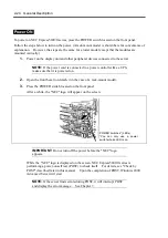
Страница 295: ...Chapter 7 Troubleshooting If the product does not work properly see this chapter before deciding that it is a breakdown ...

Страница 296: ... system operation Especially take note on whether any alert is reported to NEC ESMPRO Manager on the language PC Check whether any alert is reported on the Joint Viewer Data Viewer or Alert Viewer of NEC ESMPRO Manager Example NEC ESMPRO Manager Determine type and location of server workstation trouble ...

Страница 297: ...sages on the Liquid Crystal Display LCD The LCD on the front panel of the NEC Express5800 ft series displays the NEC Express5800 ft series status all the time If an error occurs the LCD displays the error message The following tables show the messages that are to be displayed on the LCD and explain the meanings and procedures IMPORTANT Although NEC Express5800 320Lb R does not have an LCD on its f...

Страница 298: ...k PCI module 1 2 5 V power voltage alarm lower limit Cor0 2 5vAlm 02 Amber Lit PCI module 1 Fatal 2 5 V power voltage alarm lower limit Cor0 2 5vAlm 07 Amber Blink PCI module 1 2 5 V power voltage alarm upper limit Cor0 2 5vAlm 09 Amber Lit PCI module 1 Fatal 2 5 V power voltage alarm upper limit Contact your sales agent Cor0 3 3vAlm 00 Amber Blink PCI module 1 3 3 V power voltage alarm lower limi...

Страница 299: ... module 1 Fatal 5 V power voltage alarm lower limit Cor0 5 0vsAlm 07 Amber Blink PCI module 1 5 V power voltage alarm upper limit Cor0 5 0vsAlm 09 Amber Lit PCI module 1 Fatal 5 V power voltage alarm upper limit Cor0 12vAlm 00 Amber Blink PCI module 1 12 V power voltage alarm lower limit Cor0 12vAlm 02 Amber Lit PCI module 1 Fatal 12 V power voltage alarm lower limit Cor0 12vAlm 07 Amber Blink PCI...

Страница 300: ...f not solved by the above contact your sales agent Cor0 removed Green Blink PCI module 1 PCI module detached Dismount and remount the PCI module If not solved by the above contact your sales agent Cor0 Temp Alm 00 Amber Blink PCI module 1 Temperature alarm lower limit Cor0 Temp Alm 02 Amber Lit PCI module 1 Fatal temperature alarm lower limit Cor0 Temp Alm 07 Amber Blink PCI module 1 Temperature a...

Страница 301: ...1 5 0vsAlm 07 Amber Blink PCI module 2 5 V power voltage alarm upper limit Cor1 5 0vsAlm 09 Amber Lit PCI module 2 Fatal 5 V power voltage alarm upper limit Cor1 12vAlm 00 Amber Blink PCI module 2 12 V power voltage alarm lower limit Cor1 12vAlm 02 Amber Lit PCI module 2 Fatal 12 V power voltage alarm lower limit Cor1 12vAlm 07 Amber Blink PCI module 2 12 V power voltage alarm upper limit Cor1 12v...

Страница 302: ...PU module 2 CPU 1 internal error CPU IERR 21 Green Blink CPU module 2 CPU 2 internal error CPU T Trip 00 Green Blink CPU module 1 CPU 1 thermal change error upper limit CPU T Trip 01 Green Blink CPU module 1 CPU 2 thermal change error upper limit CPU T Trip 20 Green Blink CPU module 2 CPU 1 thermal change error upper limit CPU T Trip 21 Green Blink CPU module 2 CPU 2 thermal change error upper lim...

Страница 303: ...power voltage alarm lower limit CPU0 3 3vAlm 07 Amber Blink CPU module 1 3 3 V power voltage alarm upper limit CPU0 3 3vAlm 09 Amber Lit CPU module 1 Fatal 3 3 V power voltage alarm upper limit CPU0 3 3vsAlm 00 Amber Blink CPU module 1 3 3 V power voltage alarm lower limit CPU0 3 3vsAlm 02 Amber Lit CPU module 1 3 3 V power voltage alarm lower limit CPU0 3 3vsAlm 07 Amber Blink CPU module 1 Fatal ...

Страница 304: ...ber Lit CPU module 1 Fatal temperature alarm lower limit CPU0 Temp Alm 07 Amber Blink CPU module 1 Temperature alarm upper limit CPU0 Temp Alm 09 Amber Lit CPU module 1 Fatal temperature alarm upper limit Check to see if dust is accumulated on the internal fans Check also if the fan cables are connected securely If not solved by the above contact your sales agent CPU0 VccpAlm 00 Amber Blink CPU mo...

Страница 305: ...PU module 2 Fatal 12 V power voltage alarm lower limit CPU2 12ss Alm 07 Amber Blink CPU module 2 12 V power voltage alarm upper limit CPU2 12ss Alm 09 Amber Lit CPU module 2 Fatal 12 V power voltage alarm upper limit CPU2 12v Alm 00 Amber Blink CPU module 2 12 V power voltage alarm lower limit CPU2 12v Alm 02 Amber Lit CPU module 2 Fatal 12 V power voltage alarm lower limit CPU2 12v Alm 07 Amber B...

Страница 306: ...oltage alarm upper limit CPU2 3 3vsAlm 09 Amber Lit CPU module 2 Fatal 3 3 V power voltage alarm upper limit CPU2 5 0vAlm 00 Amber Blink CPU module 2 5 V power voltage alarm lower limit CPU2 5 0vAlm 02 Amber Lit CPU module 2 Fatal 5 V power voltage alarm lower limit CPU2 5 0vAlm 07 Amber Blink CPU module 2 5 V power voltage alarm upper limit CPU2 5 0vAlm 09 Amber Lit CPU module 2 Fatal 5 V power v...

Страница 307: ...7 Amber Blink CPU module 2 CPU operating voltage alarm upper limit VCCP CPU2 VccpAlm 09 Amber Lit CPU module 2 Fatal CPU operating voltage alarm upper limit VCCP CPU2 VttAlm 00 Amber Blink CPU module 2 1 25 V power voltage alarm lower limit CPU2 VttAlm 02 Amber Lit CPU module 2 Fatal 1 25 V power voltage alarm lower limit CPU2 VttAlm 07 Amber Blink CPU module 2 1 25 V power voltage alarm upper lim...

Страница 308: ...rror Memory U Err 06 Green Blink CPU module 1 DIMM 6 2 bit error Memory U Err 21 Green Blink CPU module 2 DIMM 1 2 bit error Memory U Err 22 Green Blink CPU module 2 DIMM 2 2 bit error Memory U Err 23 Green Blink CPU module 2 DIMM 3 2 bit error Memory U Err 24 Green Blink CPU module 2 DIMM 4 2 bit error Memory U Err 25 Green Blink CPU module 2 DIMM 5 2 bit error Memory U Err 26 Green Blink CPU mod...

Страница 309: ...up menu Hard disk is faulty CPU module board is faulty PCI module board is faulty Check configuration in Setup menu Replace the hard disk Replace the CPU module board Replace the PCI module board 0210 Stuck Key Keyboard connection error Disconnect the keyboard and connect it back again Replace the keyboard Replace the PCI module board 0211 Keyboard error Keyboard is faulty 0212 Keyboard Controller...

Страница 310: ...ror RTC is faulty Replace the CPU module board 0271 Check date and time setting Date and time of RTC are incorrectly set Set the correct date and time in Setup menu Replace the PCI module board 0280 Previous boot incomplete Default configuration used Configuration error in Setup menu Check configuration in Setup menu 02B0 Diskette drive A error Floppy drive A is faulty Replace the floppy disk driv...

Страница 311: ...UP Correct device configuration in SETUP 0B43 Warning IRQ not configured Configuration error in SETUP Correct settings in SETUP 0B44 Expansion Rom not initialized Configuration error in SETUP In SETUP disable decompression of expansion ROM on unnecessary optional PCI cards 0B45 System Configuration Data Write error Configuration error in SETUP CPU PCI module board is faulty Reset the setting by se...

Страница 312: ...ilure 0B97 BMC SEL device failure BMC is faulty Replace the PCI module board 0B98 BMC SEL Overflow SEL System Event Log overflowed Erase the unnecessary SEL 0BB0 SMBIOS SROM data read error 0BB1 SMBIOS SROM data checksum bad SROM is faulty Front panel board is faulty Replace the back panel board 0BD0 1st SMBus device address not acknowledged 0BD1 1st SMBus device Error detected 0BD2 1st SMBus time...

Страница 313: ... Back panel board is faulty Replace the back panel board 0C00 Rompilot reports error number xx Configuration error in SETUP CPU PCI module board is faulty Re configure Rompilot Replace the CPU PCI module board 8600 No working DQS value found DIMM is faulty DIMM is not supported Replace DIMM Replace DIMM with appropriate one 8610 MAC Address update failed CoreI O 010 100Mbit Ethernet COntroller FRB...

Страница 314: ...en error message Cause Action 8613 MAC Address update failed CoreI O 1 Gbit Ethernet Controller FRB2 timeout occurred when setting MAC address and rewrite was unsuccessful Replace the back panel board Replace the PCI module board ...

Страница 315: ...onnect the keyboard and connect it back on If the error persists request your sales agent to replace the CPU module board 1 3 3 1 Failed to detect memory Or DIMM board type is incorrect 1 3 3 2 Initial setting error of the POST memory manager 1 3 4 1 RAM address error 1 3 4 3 RAM low byte data error 1 4 1 1 RAM high byte data error Check the installation of DIMM board If the error persists contact...

Страница 316: ...ide this data Thus copy the file into a medium e g DAT to be ready to pass it to the maintenance personnel IMPORTANT A message may appear indicating that virtual memory is insufficient when you restart the system after a STOP or system error has occurred Ignore the message and start the system NOTE Before copying the file into a medium start the Event Viewer to confirm that the Save Dump event log...

Страница 317: ... such as NEC ESMPRO Agent NEC ESMPRO Manager or GAMServer has been installed in the NEC Express5800 ft series or management PC you can obtain the error information from the display unit of the server or management PC See Chapter 5 or online documentation for details of such application programs ...

Страница 318: ...sure the power breaker for the connected power outlet is on If the power cord is plugged to a UPS make sure the UPS is powered and it supplies power See the manual that comes with the UPS for details Power supply to the server may be linked with the connected UPS using the BIOS setup utility of the server Menu to check System Hardware AC LINK Power On Make sure the POWER switch on the power unit i...

Страница 319: ... have appropriate memory boards or PCI card Operation of the server with unauthorized devices is not guaranteed Fail to access to internal or external devices Are cables properly connected Make sure that the interface cables and power cord are properly connected Also make sure that the cables are connected in the correct order Is that device compliant with NEC Express5800 ft series Operation of th...

Страница 320: ...rrect The keyboard or mouse fails to operate Is the cable properly connected Make sure that the cable is connected to the correct connector on the rear of the server Are the keyboard and mouse are compliant with NEC Express5800 ft series Operation of the server with unauthorized devices is not guaranteed Is BIOS configuration correct The keyboard and mouse may be disabled with the BIOS setup utili...

Страница 321: ... floppy disk in the floppy disk drive Refer to the manual that comes with the OS for formatting a floppy disk Fail to access to the CD ROM Is the CD ROM properly set in the CD ROM drive tray The tray is provided with a holder to secure the CD ROM Make sure that the CD ROM is placed properly in the holder Is the CD ROM applicable to the server The CD ROM for Macintosh is not available for use Is th...

Страница 322: ...e OS the OS may become unstable For update procedure see Chapter 3 The system does not operate according to the configured settings of Automatic Restart at the occurrence of error The system may or may not restart automatically even if the Automatic Restart settings are made at occurrence of an error is set If the system does not restart automatically restart it in manual mode The power cannot be ...

Страница 323: ... Although the following log may be recorded in the system event log when starting the system or after exchanging PCI modules there is no real problem on operation Change of a setup with PROSet II will become invalid if NMS service stops but you can change a setup normally because NMS service will be automatically started when PROSet II is started Source Service Control Manager Event ID 7031 Descri...

Страница 324: ...ay be logged This has no effect on the functionality of VERITAS Volume Manager Source WinMgmt ID 41 Description WMI ADAP was unable to create object index 2902 for Performance Library vxio because no value was found in the 009 subkey vmperf log is recorded in the application event log When you view the Application Event Viewer log on your computer one or more of the following events may be logged ...

Страница 325: ...vered from the failure by reinserting the PCI module for which the duplication failed Source srabb ID 98 Description Diagnostic Test Failure 10 Xena Sanity Check 0xd630 Disk information is not correct on VERITAS Enterprise Administrator after system starts If the primary PCI cannot access the FC disk the disk information may not be displayed correctly In this case run Action Update or Action Resca...

Страница 326: ...elow Message Cause and Remedy This machine is not supported This NEC EXPRESSBUILDER version is not designed for this server Execute the NEC EXPRESSBUILDER on the compliant server NvRAM access error An access to the nonvolatile memory NvRAM is not acceptable Hard disk access error The hard disk is not connected or it is failed Check whether the hard disk is correctly connected The system specific i...

Страница 327: ...incorrect Enter the correct one Failed to setup in detail for network adapter The detailed setup of network adapter is not available in setup of NEC Express5800 ft series Open the control panel after starting Windows 2000 Advanced Server to configure the network adapter Problems with Master Control Menu Failed to read online documentation Is HTML browser installed properly Online documentation is ...

Страница 328: ...rol menu fails to appear Is your system Windows NT 4 0 or later or Windows 95 or later The CD ROM Autorun feature is supported by Windows NT 4 0 and Windows 95 The older versions do not automatically start from the CD ROM Is Shift pressed Setting the CD ROM with Shift pressed down cancels the Autorun feature Is the system in the proper state The menu may not appear depending on the system registry...

Страница 329: ...ave occurred in the NEC Express5800 ft series IMPORTANT If a STOP error or system error has occurred or the system has stalled restart the system and then start collecting event logs 1 Click Start Settings Control Panel Administrative Tools Event Viewer 2 Select the type of the log to be collected Application Log contains events related to the applications that were active at occurrence of the eve...

Страница 330: ...Administrative Tools icon and then the Computer Management icon The Computer Management window appears 3 Click System Tools System Information 4 Click Save As System Information File in the Action menu 5 Enter the name of the target file in the File name box 6 Click Save Collection of Diagnostic Information by Dr Watson Collect diagnostic information related to application errors by using Dr Watso...

Страница 331: ...o restart In such a case it is required to force the server to shut down This forced shutdown however is not available if Masked is selected for Power Switch Mask on the Security menu of the BIOS setup utility SETUP because this setting disables POWER switch operation Follow the procedure below to change the setting to enable the forced shutdown and restart of the server 1 Power on the server and ...

Страница 332: ...eate a Windows 2000 OEM DISK for EXPRESSBUILDER 1 Prepare a 3 5 inch floppy disk 2 Power on the peripherals and then NEC Express5800 ft series 3 Modify the BIOS settings Select Advanced Monitoring Configuration and Disable the settings of Boot Monitoring 4 Insert the EXPRESSBUILDER CD ROM into the drive of the server 5 Then reset pressing Ctrl Alt Delete or power off on NEC Express5800 ft series t...

Страница 333: ...ppy disk Write protect and place a label on the disk and keep it in a safe place If you have an update CD ROM NEC Express5800 ft Series ft Control Software Ver n n Follow the steps below to create a Windows 2000 OEM DISK for EXPRESSBUILDER 1 Prepare a 3 5 inch floppy disk 2 Insert the update CD ROM into the drive of a computer that runs Windows 2000 NT or Windows 95 98 Me 3 From the Start menu sel...

Страница 334: ...t until message Press F6 if appears on the screen 8 Press the F5 and F6 quickly IMPORTANT If you press neither the F5 nor F6 the repair process is not started 9 If the text base setup is started follow the directions on the screen to proceed As you follow the directions the screen for selecting HAL will appear 10 Insert the Windows 2000 OEM DISK for EXPRESSBUILDER into the floppy disk drive and sp...

Страница 335: ...air disk After the disk is reviewed the system is restarted once NOTE The processes without use of the system repair disk are performed 17 Repeat Steps 1 to 15 above The repair process is started During the repair process unfound or defected files are replaced with the corresponding files in C 1386 of the hard disk or the systemroot Repair folder of the system partition The configuration changes p...

Страница 336: ...7 42 Troubleshooting This page is intentionally left blank ...

Страница 337: ...es not assume any liability for damage to optional devices or the server or malfunctions of the server resulted from installation by the user NEC recommends you ask your sales agent to install or remove any optional devices Be sure to use only optional devices and cables designated by NEC Repair of the server due to malfunctions failures or damage resulted from installing such devices or cables wi...

Страница 338: ... repair or alter the server Do not look into the CD ROM drive Do not remove the lithium battery Disconnect the power plug before working with the server CAUTION Observe the following instructions to use the server safely Failure to follow these instructions may cause a fire personal injury or property damage See safety precautions in for details Do not install or remove components by a single pers...

Страница 339: ...suitable workspace Work with the server on the anti static or concrete floor When you work with the server on a carpet where static electricity is likely to be generated make sure take anti static measures beforehand Use a worktable Place the server on an anti static mat to work with it Clothes Do not wear a wool or synthetic cloth to work with the server Wear anti static shoes to work with the se...

Страница 340: ...uring the continuous operation disable the intended module place the module off line by using the ft series utility of the NEC ESMPRO Agent or the NEC ESMPRO Manager from the management PC on the network After a new module is installed to the server enable the module using the ft series utility or the NEC ESMPRO Manager NOTE The system is defaulted to automatically boot the module once installed T...

Страница 341: ...ror is likely to be issued when the hard disk drive processing cannot keep up in time with requests of the OS but the processing is carried on normally thanks to the retry function So this does not affect the operation at all In case such an error is issued check the detailed data indicated below and if it is f0030004 or f0030015 just ignore that log If however a SCSI controller error whose detail...

Страница 342: ...e groups The figure below shows the groups and mirroring slots Empty slots in the hard disk bay contain dummy trays The dummy trays are inserted to improve the cooling effect within the device Always insert the dummy trays in the slots in which hard disks are not installed Attach an HDD ID label indicating the slot number of installed hard disk to the handle of the hard disk Group 1 Group 2 Slots ...

Страница 343: ...disks as dual disk 1 Shutdown Windows 2000 Advanced Server The system turns off automatically and the POWER LED goes off 2 Disconnect all the power cords from the power outlet 3 Tower model Unlock the front bezel with the security key and open it Rack mount model Unlock the front bezel with the security key and remove the upper and lower panels 4 Identify the slot to which you want to install the ...

Страница 344: ... the lever and handle NOTE Check the hook of the lever is engaged with the frame 9 Connect all the power cords 10 Press the POWER switch to turn on the system power 11 Tower model Close the front bezel and lock it with the security key Rack mount model Install the upper and lower panels and lock the front bezel with the security key A while after Windows 2000 Advanced Server is started New Hardwar...

Страница 345: ...goes off 2 Disconnect all the power cords from the power outlet 3 Tower model Unlock the front bezel with the security key and open it Rack mount model Unlock the front bezel with the security key and remove the upper and lower panels 4 Push the lever of the hard disk to unlock the handle 5 Hold the handle and hard disk to pull them off 6 Install the dummy tray in an empty tray according to proced...

Страница 346: ...ing the hard disk remove the failed hard disk No need to shutdown Windows 2000 Advanced Server 3 Refer to the steps in Installing the hard disk to install a new hard disk NOTE The hard disk to be installed for replacement must have the same specifications as its mirroring hard disk Use an unsigned hard disk to replace the failed one If you use a signed disk you need to restore the redundant config...

Страница 347: ...e the path information in General Information of SCSI Slot to locate a group of 3 5 inch device bays that corresponds to each enclosure The table below shows the path information on Groups 1 and 2 Slot PCI module SCSI adapter SCSI bus Group1 10 5 0 Group2 11 5 0 3 See the path information in General Information of SCSI Slot ID 10 40 1 It shows that PCI module SCSI adapter and SCSI bus are 10 5 and...

Страница 348: ... Upgrade corresponds to SCSI slots under SCSI Enclosure ID 11 40 You will find that the failed disks located in SCSI slots ID 10 40 2 and ID 11 40 3 are the 2nd disk of Group 1 and 3rd disk of Group 2 respectively ...

Страница 349: ...ROM DOS Startup FD see Chapter 5 NEC EXPRESSBUILDER Top Menu Tool Create Support Disk of the User s Guide Short time after ROM DOS starts up the A prompt will appear 3 Execute the FDISK command 4 Select 3 Delete partition or Logical DOS Drive from the menu 5 Select 4 Delete Non DOS Partition from the menu and delete the area according to the messages 6 Repeat Step 5 until deleting all the areas 7 ...

Страница 350: ... for the basic procedure IMPORTANT If you need to remove a hard disk due to a failure identify that hard disk on Data Viewer not the disk number on VERITAS Enterprise Administrator When you make resetting of the mirrors see the target IDs of Device types listed in Properties not the disk numbers on VERITAS Enterprise Administrator If a hard disk included a Boot volume if it was used to store OS yo...

Страница 351: ... F are included broke Some disks are indicated as Unknown disk However they may be indicated differently depending on the error type Even in such cases failed disks can be recovered by following the steps below 5 Remove the hard disks from Slot 2 of Group 1 and Slot 3 of Group 2 6 Open VERITAS Enterprise Administrator 7 Select a volume that has x and view the mirror tab 8 Right click the degenerat...

Страница 352: ...o see if the degenerate disk is selected click Yes At Drive F Mirror and Degenerate will change to Connected and Normal 10 At DynamicGroup right click Unknown disk that no longer has any volumes and select Erase disk from Dynamic Disk Group ...

Страница 353: ...System Upgrade 8 17 11 After checking to see if Unknown disk is selected click OK 12 In the same way erase the other Unknown disk ...

Страница 354: ...group IMPORTANT If you add a used disk do the following steps If Unknown disk group appears Perform Disk outer join Then erase Unknown disk as described in Steps 7 to 11 above Erase the volumes and perform Erase disk from dynamic disk group Follow the wizard to perform Add disk to dynamic disk group If Different format appears Perform Erase disk from dynamic disk group Then follow the wizard to pe...

Страница 355: ...System Upgrade 8 19 15 Check the disk you selected and click Next 16 Click Complete ...

Страница 356: ... disks are numbered at the time of OS startup based on their inserted positions After the OS startup each time you insert a new hard disk a larger number will be given When you restart the OS the hard disks will be numbered again based on their inserted position regardless of their former numbers Since disk numbers change due to restartup in this way you need to make mirror setting of disks based ...

Страница 357: ... manually select Disk 1 and click Select After checking to see if the configuration is correct click OK to add the mirror NOTE Although Disks 1 and 4 are mirrored in this example other disks may be selected at the default If so click Modify select Disk 1 and click OK 20 In the same way make a mirror setting of Disks 2 and 5 Upon completion of synchronous processing recovery is completed ...

Страница 358: ...n the Case of Stripe Volume Mirroring The following is a procedure of mirror recovery for stripe volumes In this example stripe volumes are mirrored as shown below The figure below shows View Disk tab of Dynamic Disk Group ...

Страница 359: ...ipe volume The next procedure is to perform recovery when Disk 2 fails in the above environment 1 Check disks If a failure occurs on a disk that includes a mirror volume the volume will show Degenerate status Its disk name will change to Unknown Disk and x will appear on its disk icon will appear on the failed disk and on the stripe volume disk If you click View Disk tab of Unknown Disk marks are ...

Страница 360: ... locate failed disks see How to Locate Failed Disks above 3 Erase stripe volume mirrors on Unknown Disk After selecting Volume E on Unknown Disk right click a mirror with x on Mirror tab and select Erase Mirror When a confirmation message appears click Yes After you erase the mirrors Volumes E in Disks 4 and 5 change from Degenerate to Normal dynamic stripe volume ...

Страница 361: ... G as well After you erase all volume mirrors on Unknown Disk there are no volumes on Unknown Disk and the space of Disk 1 which made up stripe volumes with Disk 2 is empty 4 Erase Unknown Disk Right click Unknown Disk and select Erase Disk from Dynamic Disk Group ...

Страница 362: ...ks above 6 Create mirrors for each stripe volumes Create mirrors of disks based on their target IDs in Disk Properties not their disk numbers in View Disk In this example create mirrors between Disks 1 and 4 and between Disks 2 and 5 For details of disk combination see Step 17 of In the Case of Simple Volume Mirror above Use Add Mirror to add a new mirror in the new disk s space At Disk 4 or 5 rig...

Страница 363: ...e of Span Volume Mirror The following is a procedure of mirror recovery for span volumes In this example span volumes are mirrored as shown below Volumes E are span volumes The figure below shows View Disk tab of Dynamic Disk Group ...

Страница 364: ... a failure occurs on a disk that includes a mirror volume the volume will show Degenerate status Its disk name will change to Unknown Disk and x will appear on its disk icon will appear on the failed disk and on the stripe volume disk 2 Locate the failed disk and remove it from the slot For procedures to locate failed disks see How to Locate Failed Disks above 3 Erase span volume mirrors on Unknow...

Страница 365: ... Different Format or Unknown Disk right click the disk in View Disk select Erase Disk from Dynamic Disk Group and select Add Disk to Dynamic Disk Group IMPORTANT You need to format a used hard disk before reusing it in a disk dual configuration Perform the steps described in How to Format Disks above 6 Create mirrors Create mirrors of disks based on their target IDs in Disk Properties not their di...

Страница 366: ... with different target IDs may be combined if other disks have free space In this case you can make correct combinations by creating temporary volumes in such free space Select Select Disk Manually and check to see if the mirror combinations are correct Erase the temporary volumes you created before Upon completion of synchronous processing recovery is completed ...

Страница 367: ...re installing or removing options To install or remove CPU or DIMM first power off the server before removing the CPU module The procedures described below are for replacement of DIMMs Removing the module being operating may cause unexpected trouble Use the management software e g ft series utility or NEC ESMPRO Manager to identify the module to be removed so that the module is removed when it is ...

Страница 368: ...lect FTServer CPU Module CPU Module to be removed Bring Up Bring Down Down After the CPU module enters into off line status the status LED will change as follows Fail LED Red State LED Off 2 Tower model Unlock the front bezel with the security key and open it Rack mount model Unlock the front bezel with the security key and remove the upper and lower panels 3 Loosen the setscrews that secured the ...

Страница 369: ...lease lever to pull the module Carefully handle the CPU module so that you will not drop it or strike it against other server internal devices 7 Carefully place the CPU module on the flat and sturdy table Avoid the dusty or humid place 8 Remove the two setscrews on the front of the CPU module and one setscrew on the back 9 Slide the top cover a little to remove it Release lever Release lever Latch...

Страница 370: ...8 34 System Upgrade This allows you to access the devices in the CPU module For more information on how to handle these devices see the associated sections ...

Страница 371: ... Install the top cover to the CPU module NOTE Check the left right and upper tabs on the cover are certainly engaged with the CPU module 2 Secure the top cover to the CPU module with the three setscrews 3 Firmly hold the CPU module with both hands and insert it into the server Hold the module in such a way that its back plane connector faces the back of the rack and engage the guides of the module...

Страница 372: ...r as it goes 6 Hold the release lever to push the module as far as it goes 7 Close the release lever IMPORTANT Unless the release levers are located inside the rack frame the module won t be mounted correctly 8 Screw the release levers Release levers Latch lever Wrong The hook is located behind the frame Correct The hook is located above the frame ...

Страница 373: ...ility of the NEC ESMPRO Agent installed to the server or the Data Viewer of the NEC ESMPRO Manager For the detailed procedure see NEC ESMPRO Agent and Manager Maintenance of NEC Express5800 ft series in Chapter 5 NEC ESMPRO Manager Select FTServer CPU Module installed CPU Module Maintenance Bring Up Bring Down Bring Up ft series utility Select FTServer CPU Module installed CPU Module Bring Up Brin...

Страница 374: ...he group corresponds to the connector number shown in the figure below IMPORTANT The DIMM is extremely sensitive to static electricity Make sure to touch the metal frame of the server to discharge static electricity from your body before handling the DIMM Do not touch the DIMM terminals or on board parts with a bare hand or place the DIMM directly on the desk For static notes see the section Anti ...

Страница 375: ...n a DIMM is added to one group another identical DIMM should be installed to the socket with the same number in another group This rule is applied to the case of removal The linked DIMMs should be of the same product with same performance DIMMs should be installed in sockets starting from the lowest socket number CPU module board ...

Страница 376: ...d the POWER LED goes off 2 Disconnect power cord from outlet 3 Remove the CPU module 4 Check to be sure in which socket you are mounting the DIMM 5 Remove the connector cover from the socket A DIMM connector cover is installed to the open socket When the levers on both ends of the connector are opened the DIMM connector cover is unlocked and you can remove the cover IMPORTANT Carefully keep the re...

Страница 377: ...o the socket the levers are automatically closed 7 Mount the CPU module 8 Connect the power cords 9 Press POWER switch to power on the module 10 Verify that POST displays no error messages If POST displays an error message take a note on the massage and see the POST error messages listed in Chapter 7 11 After starting the OS set the paging file size to at least the recommended value 1 5 times the ...

Страница 378: ...rns off automatically and the POWER LED goes off 2 Disconnect power cord from outlet 3 Remove the CPU module 4 Open the levers on the target DIMM socket The DIMM is unlocked and you can remove the device 5 Mount the CPU module 6 Connect the power cable 7 Press the POWER switch to power on the module 8 Verify that POST displays no error messages If POST displays an error message take a note on the ...

Страница 379: ...edure below to replace the failed DIMM 1 Identify the failed DIMM using the Data Viewer of the NEC ESMPRO Manager 2 Remove the CPU module 3 Replace a DIMM 4 Install the CPU module 5 Boot the CPU module using the NEC ESMPRO Manager or ft series utility ...

Страница 380: ...ctly on the desk For static notes see the section Anti static Measures described earlier Do not use the system before checking to see it works correctly Make sure to use the CPU authorized by NEC Installing a third party CPU may cause a failure of the CPU as well as the server Repair of the server due to failures or damage resulted from installing such a board will be charged Before adding or remo...

Страница 381: ...ff automatically 2 Unplug the power cord 3 Remove the CPU module 4 Detach the CPU air duct 5 Check to be sure of the location of the CPU socket 6 Remove the anti dust sheet from the socket IMPORTANT Carefully keep the removed sheet 7 Lift the socket lever IMPORTANT Open the lever fully It can be opened 120 or more ...

Страница 382: ... heat radiation sheet one piece on top of the CPU Place the sheet to cover the chip segment IMPORTANT Since a cool sheet is very easy to break you need to handle it carefully If it breaks replace it with new one It cannot be reused Use one sheet for one CPU Do not place more than one sheet on a single CPU Keep the rest of the sheets for future use Sometimes a cool sheet has already been affixed on...

Страница 383: ...rd IMPORTANT If the heat sink is not parallel to the motherboard dismount and remount it You cannot mount the heat sink correctly due to the following CPU is not mounted correctly The heat sink clip is not engaged correctly Do not hold the fastened heat sink to move the CPU 14 Attach the CPU air duct NOTE Check to see if the air duct is attached securely with its projected parts inserted into the ...

Страница 384: ...elow to remove the CPU Except when you replace the CPU with a new one power off the server IMPORTANT Do not remove the CPU unless it is faulty If a CPU is not mounted on CPU 2 cover it with an anti dust sheet After operation the cool sheet at the bottom of the heat sink may stick to the CPU because of heat When you dismount the heat sink turn it lightly to make sure that the heat sink is not stick...

Страница 385: ...or message take a note on the massage and see the POST error messages listed in Chapter 7 Replacing CPU Follow the steps below to replace a failed CPU 1 Use Data Viewer of NEC ESMPRO Manager to check the failed CPU 2 Remove the CPU module 3 Replace the CPU 4 Install the CPU module 5 Start the CPU module from ft Series Utility or NEC ESMPRO Manager In the initial setting the server will start up au...

Страница 386: ...ures used in this section show the tower model The orientation is the only difference from the rack mount model IMPORTANT Ask your sales agent to replace the cooling fan and PCI module Make sure to read Anti static Measures and Preparing Your System for Upgrade before starting installing or removing options Handle the module fixing screw with your hand not by using any tool If you have replaced th...

Страница 387: ...Status Off Primary Blinking in red Secondary At 1 second intervals Do not remove the PCI module on Primary BMC side BMC Sync disabled Off Primary Lit in red Secondary Do not remove either PCI modules During BMC Sync Off Primary Blinking in red Secondary At 0 5 second intervals Do not loosen a screw securing the PCI module or turn off the system power while the LED is blinking in red When DC power ...

Страница 388: ...ee NEC ESMPRO Agent and Manager Maintenance of NEC Express5800 ft series in Chapter 5 NEC ESMPRO Manager Select FTServer PCI Module PCI Module to be removed Maintenance Bring Up Bring Down Bring Down ft series utility Select FTServer PCI Module PCI Module to be removed Bring Up Bring Down Down After the CPU enters into off line status the status LEDs of the PCI board and PCI module will change as ...

Страница 389: ...ward you 6 Firmly hold the handle and pull the PCI module slowly and carefully until the main unit is locked IMPORTANT Do not hold the other parts than the release lever to pull the module 7 Pull off the module pushing down the latch lever to unlock it When half of the module is pulled out ask another person to support it IMPORTANT Do not hold the other parts than the release lever to pull the mod...

Страница 390: ...ews on the front of the PCI module and one setscrew on the back 10 Slide the top cover a little to remove it This allows you to access the devices in the PCI module For more information on how to handle these devices see the associated sections ...

Страница 391: ...ged with the PCI module 2 Secure the top cover to the PCI module with the three setscrews 3 Firmly hold the PCI module with both hands and insert it into the server 4 Hold the module in such a way that its back plane connector faces the back of the rack and engage the guides of the module and chassis to insert it slowly 5 Hold and push the release lever until the module is locked IMPORTANT Do not ...

Страница 392: ...e release lever IMPORTANT Unless the release levers are located inside the rack frame the module won t be mounted correctly 9 Screw the release levers Release lever Latch lever Release lever Wrong The hook is located behind the frame Correct The hook is located above the frame ...

Страница 393: ...lity of the NEC ESMPRO Agent installed to the server or the Data Viewer of the NEC ESMPRO Manager For more information see NEC ESMPRO Agent and Manager Maintenance of NEC Express5800 ft series in Chapter 5 NEC ESMPRO Manager Select FTServer PCI Module installed PCI Module Maintenance Bring Up Bring Down Bring Up ft series utility Select FTServer PCI Module installed PCI Module Bring Up Bring Down ...

Страница 394: ...talling or removing options PCI 1 is a slot dedicated for video board which is standard equipment Do not replace this broad with any other board TIPS When a PCI board is installed or removed or the slot is changed use the BIOS setup utility SETUP to change the detailed settings such as interrupt line IRQ when necessary See Appendix B for details Note the followings to install or replace PCI board ...

Страница 395: ...le s top cover 3 Identify the slot to which you want to install a PCI board and remove the connector cap IMPORTANT Carefully keep the removed connector cap 4 To install a long card loosen the setscrew slide the bracket and secure it with the setscrew 5 Pull the PCI board retainer bracket from the inside 6 Unscrew the setscrew of the additional slot cover at the same position level as the target sl...

Страница 396: ...he board slowly into the slot NOTE Check to see if the edge of the bracket taper is inserted into a slot of the chassis In the case of a long board check also to see if its other edge is inserted into the bracket guide PCI board retainer bracket Additional slot cover Guide Slots for inserting bracket edges ...

Страница 397: ...de rail groove and insert the board slowly IMPORTANT If the insertion is unsuccessful remove the board once and retry installation Note that if excessive force is applied to the board it may be damaged 9 Attach the retainer bracket to fasten the PCI board ...

Страница 398: ...guration In the initial setting the server will start up automatically upon mounting the PCI module If it is set not to start up automatically use Data Viewer of NEC ESMPRO Manager or ft Series Utility to start it For more information refer to NEC ESMPRO Agent and Manager Maintenance of NEC Express5800 ft series in Chapter 5 17 Check the PCI module status LED and PCI board status LED For descripti...

Страница 399: ...System Upgrade 8 63 Cable ties included with cabinet ...

Страница 400: ...e release lever at this time 9 Connect the network cable and option cables 10 Close the release lever 11 Secure the release lever with the setscrew 12 Boot the PCI module using the NEC ESMPRO Manager or ft series utility to establish a dual configuration In the initial setting the server will start up automatically upon mounting the PCI module If it is set not to start up automatically use Data Vi...

Страница 401: ... 7 Install the PCI module Do not close the release lever at this time 8 Connect the network cable and option cables 9 Close the release lever 10 Secure the release lever with the setscrew 11 Boot the PCI module using the NEC ESMPRO Manager or ft series utility to establish a dual configuration In the initial setting the server will start up automatically upon mounting the PCI module If it is set n...

Страница 402: ...o change the Boot Monitoring Time out Period configuration in Advanced Monitoring Configuration For more details see page 4 15 N8803 002F SCSI Controller Slots to install the board PCI slot Group 1 Group 2 N code Name 1 2 3 1 2 3 Remarks N8803 002F SCSI controller Each PCI module can contain one board only Can be installed Cannot be installed Installation of driver When you start the system with t...

Страница 403: ...gh the PCI board is mounted it may be offline or not be working Remount the PCI board correctly Remount the PCI module correctly When not solved contact your sales agent N8804 001P1 100BASE TX Adapter Set Slots to install the board PCI slot Group 1 Group 2 N code Name 1 2 3 1 2 3 Remarks N8804 001P1 100BASE TX adapter set 100BASE TX Adapter Can be installed Cannot be installed Installation of driv...

Страница 404: ...s Description Action Green Duplex is specified however the server works in simplex mode Specify duplex AFT ALB Specify an appropriate driver PCI board is properly installed and operates in non duplex mode AFT ALB Does not depend on simplex or duplex In non duplex mode no special problem occurs POST is operating or the PCI board is installed to operate in the duplex mode The system is operating nor...

Страница 405: ...lers in pairs Insert a Fibre Channel Controller into a slot in a PCI module and another Fibre Channel Controller into the slot at the same location in another PCI module PCI Board Status LED Indications LED indications Description Action PCI board is mounted correctly and operates in duplex mode The system operates normally Off The PCI board is not mounted is mounted incorrectly or power is not su...

Страница 406: ...ng the drivers in the following procedure perform a dual configuration setup TIPS To perform this procedure you have to log on the system as an Administrator or a member of the Administrators group After installing the OS follow the steps below to install a driver and establish a dual configuration 1 Mount the N8104 84 adapter to the slot with the same number in PCI module 1 and 2 and then start t...

Страница 407: ...erating normally in duplex mode Off The PCI board is not installed yet the PCI board is installed incorrectly or the power is not supplied Mount the PCI board correctly If the PCI board was not mounted there is no problem Check the condition of power unit Remount the PCI module The PCI board is not mounted is mounted incorrectly or power is not supplied Wait for a while until the indication change...

Страница 408: ...stalling the drivers in the following procedure perform a dual configuration setup TIPS To perform this procedure you have to log on the system as an Administrator or a member of the Administrators group After installing the OS follow the steps below to install a driver and establish a dual configuration 1 Mount the N8104 103 adapter to the slot with the same number in PCI module 1 and 2 and then ...

Страница 409: ...erating normally in duplex mode Off The PCI board is not installed yet the PCI board is installed incorrectly or the power is not supplied Mount the PCI board correctly If the PCI board was not mounted there is no problem Check the condition of power unit Remount the PCI module The PCI board is not mounted is mounted incorrectly or power is not supplied Wait for a while until the indication change...

Страница 410: ...8 74 System Upgrade This page is intentionally left blank ...
Страница 411: ...nterface 1 Load on tray type x24 speed A ready drive is indicated by POWER LED of that PCI module 5 25 inch None File bay 3 5 inch 6 slots PCI 6 slots Additional slot 2 slots are used for graphics board LAN interface 1000BASE T 100BASE TX 10BASE T 2 ports 100BASE TX 10BASE T 2 ports USB 4 pin 2 ports 2 ports are used by keyboard and external USB FDD Serial D sub 9 pin 2 ports Network RJ 45 4 ports...

Страница 412: ...A 2 Specifications This page is intentionally left blank ...
Страница 413: ...g interface DMA controller page register Base address register Register IRQ13 Logical device configuration EDMA2 compatible mode primary command block register EDMA2 compatible mode secondary command block register Parallel port 3 Serial port 2 EDMA2 compatible mode secondary command block register Floppy disk drive 2 IDE 2 Parallel port 2 VGA Parallel port 1 VGA EDMA2 compatible mode primary comm...

Страница 414: ... interface IPMI SCI SW1 interface Power management index register Power management data register PCI configuration space Reset control General chipset EDMA2 PCI base address register 4 Expressed in hexadecimal digits I O port addresses of PCI devices are specified based on the type and number of PCI devices ...

Отзывы: