7-10 Troubleshooting
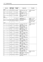
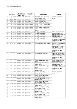
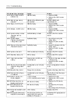
STATUS LED
Indication
Color
State
Suspected
module
Explanation Procedure
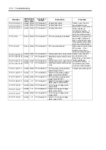
CPU0 FAN Alm 01
Amber Blink CPU module #1
Cooling fan1 alarm
CPU0 FAN Alm 03
Amber Blink CPU module #1
Cooling fan2 alarm
CPU0 FAN Alm 04
Amber Blink CPU module #1
Cooling fan3 alarm
Check to see if dust is
accumulated on the
internal fans. Check also if
the fan cables are
connected securely. If
not solved by the above,
contact your sales agent.
CPU0 offline
Green
Blink CPU module #1
PCI module logically isolated
Start the PCI module by ft
sever utility or dismount
and remount that module.
If not solved by the above,
contact your sales agent.
CPU0 removed
Green
Blink CPU module #1
PCI module detached
Dismount and remount the
PCI module. If not
solved by the above,
contact your sales agent.
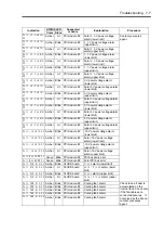
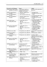
CPU0 Temp Alm 00
Amber Blink CPU module #1
Temperature alarm (lower limit)
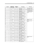
CPU0 Temp Alm 02
Amber
Lit
CPU module #1 Fatal temperature alarm (lower
limit)
CPU0 Temp Alm 07
Amber Blink CPU module #1
Temperature alarm (upper limit)
CPU0 Temp Alm 09
Amber
Lit
CPU module #1
Fatal temperature alarm (upper
limit)
Check to see if dust is
accumulated on the
internal fans. Check also if
the fan cables are
connected securely. If
not solved by the above,
contact your sales agent.
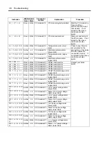
CPU0 VccpAlm 00
Amber Blink CPU module #1
CPU operating voltage alarm
(lower limit) (VCCP)
CPU0 VccpAlm 02
Amber
Lit
CPU module #1
Fatal CPU operating voltage
alarm (lower limit) (VCCP)
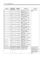
CPU0 VccpAlm 07
Amber Blink CPU module #1
CPU operating voltage alarm
(upper limit) (VCCP)
CPU0 VccpAlm 09
Amber
Lit
CPU module #1
Fatal CPU operating voltage
alarm (upper limit) (VCCP)
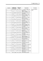
CPU0 Vtt Alm 00
Amber Blink CPU module #1
1.25-V power voltage alarm
(lower limit)
CPU0 Vtt Alm 02
Amber
Lit
CPU module #1
Fatal 1.25-V power voltage
alarm (lower limit)
CPU0 Vtt Alm 07
Amber Blink CPU module #1
1.25-V power voltage alarm
(upper limit)
CPU0 Vtt Alm 09
Amber
Lit
CPU module #1
Fatal 1.25-V power voltage
alarm (upper limit)
Contact your sales agent.
Содержание Express5800/320Lb FT Linux
Страница 1: ...N8800 027F 028F NEC Express5800 320Lb 320Lb R User s Guide 1st Edition 02 2003 856 122693 901 A ...
Страница 10: ...iv This page is intentionally left blank ...
Страница 16: ...x This page is intentionally left blank ...
Страница 19: ...Precautions for Use 1 3 Label A Label B Label C Label E Label D ...
Страница 20: ...1 4 Precautions for Use Rack mount model Label B Label A Label C Label D ...
Страница 21: ...Precautions for Use 1 5 Label D Label C Label B Label A ...
Страница 22: ...1 6 Precautions for Use PCI CPU Modules PCI Module CPU Module Label A Label A Label A ...
Страница 36: ...1 20 Precautions for Use This page is intentionally left blank ...
Страница 44: ...2 8 General Description Front View inside Tower model Rack mount model ...
Страница 70: ...2 34 General Description This page is intentionally left blank ...
Страница 71: ...Chapter 3 Setup This chapter describes setup procedures to make NEC Express5800 ft series ready for use ...
Страница 118: ...3 48 Setup This page is intentionally left blank ...
Страница 162: ...4 44 System Configuration This page is intentionally left blank ...
Страница 217: ...Installing and Using Utilities 5 55 Also at this time the state of the mirrored disks change to Normal Mirror Disk ...
Страница 294: ...6 14 Maintenance This page is intentionally left blank ...
Страница 295: ...Chapter 7 Troubleshooting If the product does not work properly see this chapter before deciding that it is a breakdown ...
Страница 336: ...7 42 Troubleshooting This page is intentionally left blank ...
Страница 355: ...System Upgrade 8 19 15 Check the disk you selected and click Next 16 Click Complete ...
Страница 399: ...System Upgrade 8 63 Cable ties included with cabinet ...
Страница 410: ...8 74 System Upgrade This page is intentionally left blank ...
Страница 412: ...A 2 Specifications This page is intentionally left blank ...


