2205B0JE-DA-J-N_2014.05.
2 Structure and Specifications of the Compressor
Screw Compressor J-series
2.8 Variable Vi Control
2-28
2.8
Variable Vi Control
2.8.1 Vi (Internal Volume Ratio)
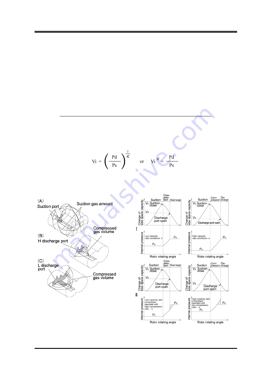
For a screw compressor, the volume of refrigerant gas trapped between the M and F rotor lobes
decreases while the pressure increases as the rotors turn. When the trapped volume decreases to the
designed Vi (internal volume ratio), the volume is exposed to the discharge side and the refrigerant gas
is discharged.
As described above, for a screw compressor, the Vi (internal volume ratio) indicates the ratio of the
volume of sucked refrigerant gas to the compressed minimum volume when the interlobes connect to
the discharge outlet port (the volume before discharged).
Vi is shown as follow.
Vi =
(Volume of refrigerant gas (after suction) when compression begins)
(Volume of refrigerant gas when discharge port opens (end of compression))
Vi is the ratio of the volume between rotor lobes and casing after completion of suction and the volume
when discharge port starts to open. The J-series basically adopts three Vi values of 2.50, 3.50, and 5.0
which are called ‘L port’, ‘M port’, and ‘H port’ respectively.
Vi is expressed as follows with the compression ratio.
As shown above, Vi is related to the specific heat ratio (
κ
) of the refrigerant gas. Therefore, Vi values
vary not only with the compression ratio but also the type of refrigerant gas. The J-series compressors
are designed to automatically adjust Vi according to operating conditions using the specified controller
(MYPRO-CP IV or succession machine).
Figure 2-24 Explanation of Vi (Internal
Volume Ratio)
Figure 2-25 Relationship between Vi Settings
and Operation Conditions


