2205B0JE-DA-J-N_2014.05.
5 Maintenance and Inspection
Screw Compressor J-series
5.4 Disassembly and Assembly of the Compressor
5-56
5.4.16.1 Precautions for Removal
Thrust bearing gland
1.
Protect the part of the male rotor where the mechanical seal is installed from being damaged by
using a curing tape.
Locknuts M and F / torsional slip washers / lock washers M and F
1.
Using a screwdriver, bend back the claw of
the lock washer.
Thrust bearing assembly for male rotor / thrust bearing assembly for female rotor
If the thrust bearings cannot be removed by hand, use the thrust bearing pulling tool. Take care
not to damage the inner and outer rings, balls and retainers of the thrust bearings.
5.4.16.2 Precautions for Installation
Thrust
bearing
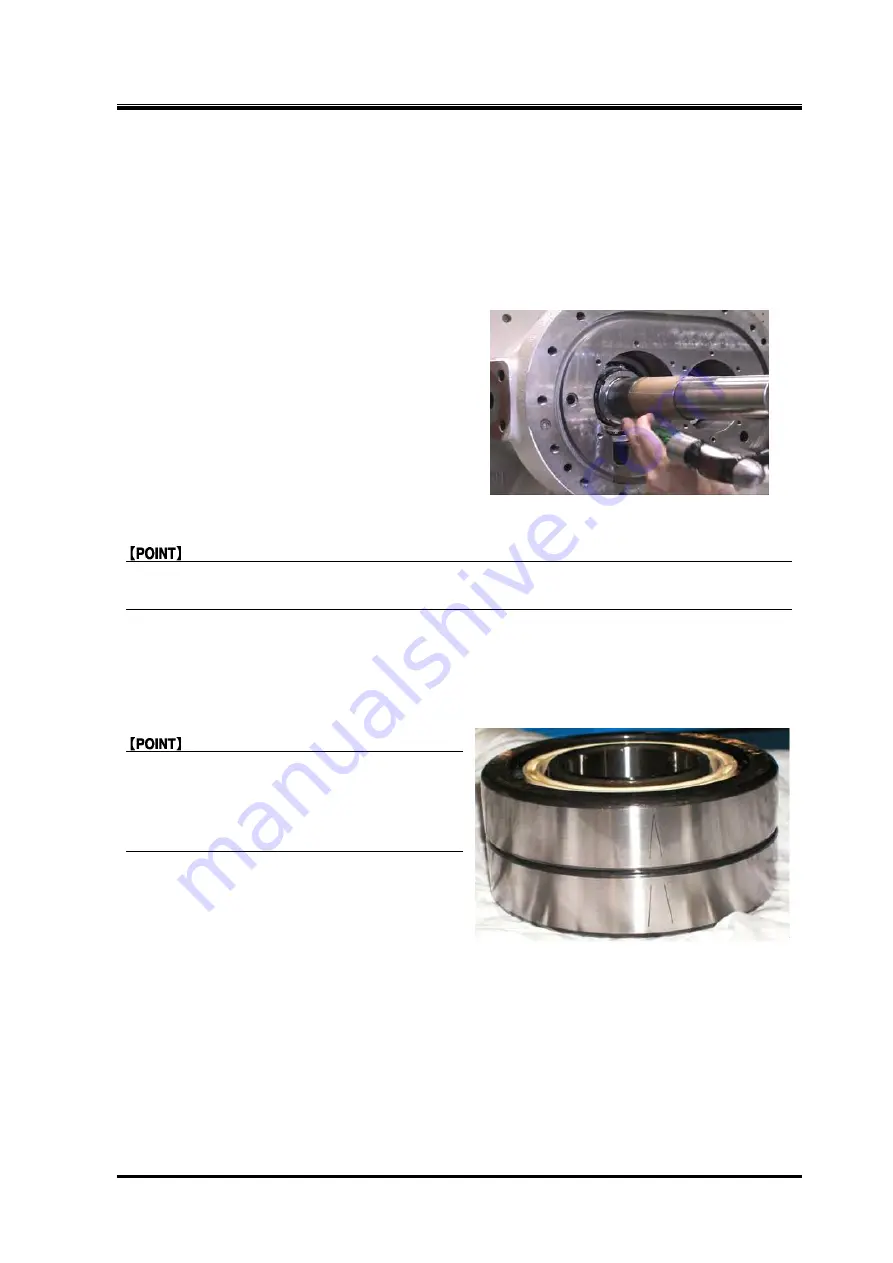
When replacing the thrust bearings, regarding
the direction of thrust bearing assembly, there
may or may not be a V-shaped mark for
assembly on the outer side of the bearing.
Follow the instructions below accordingly.
1.
If there is a V-shaped mark for assembly on
the outer side of the thrust bearing, assemble
with the pointed end of the mark on the inner
side of the machine due to a slight directional
difference that affects end clearance
adjustment.
If there is no V-shaped mark, assembly direction does not affect end clearance adjustment.
However, to clarify the difference between the inner side and outer side of the machine, after
assembling with the bearing number engravings on the outer side, make a V-shaped mark using
blue whetstone on the machine’s inner side of the bearing..


