Chapter 3 Installation
UD-series Screw Compressor
3.2 Installation Works
3-5
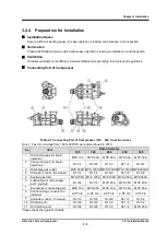
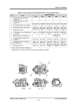
Table 3-2 Connecting Port of Compressor (125 – 320, Cast steel case)
No.
Item
Rotor diameter
125
160
200
250
320
1
Connecting port for liquid
injection 1
2
Connecting port for liquid
injection 2
3
Discharge gas outlet
(
type D
)
ANSI #300
3”
ANSI #300
3”
ANSI #300
5”
ANSI #300
6”
ANSI #300
8”
4
Unloader control
(
decrease
)
NPT 1/4
NPT 1/4
NPT 3/8
NPT 3/8
NPT 3/8
5
Suction gas inlet
ANSI #300
4”
ANSI #300
5”
ANSI #300
6”
ANSI #300
10”
ANSI #300
14”
6
Lubricating oil main supply port
(
journal
)
NPT 3/8
ANSI #300
1/2”
ANSI #300
3/4”
ANSI #300
1”
ANSI #300
1 1/2”
7
Economizer connecting port
ANSI #300
1 1/2”
8
Control wiring connector for
indicator
2-PF 3/4
2-PF 3/4
2-PF 3/4
2-PF 3/4
2-PF 3/4
9
Unloader control
(
increase
)
NPT 1/4
NPT 3/8
NPT 3/8
NPT 1/2
NPT 1/2
10 Oil drain port
NPT 3/8
NPT 3/8
NPT 1/2
NPT 1/2
NPT 1/2
11
Oil injection port
NPT 3/8
NPT 3/8
ANSI #300
1/2”
ANSI #300
1/2”
ANSI #300
1”
・
Please contact us for the blank size.
・
It may differ from the above table. Please check the figure for details.
Figure 3-3 Connecting Port of Compressor
(
400
)

