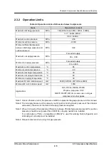
Chapter 2
Compressor Specifications and Structure
UD-series Screw Compressor 2.4
Compressor Structure and Mechanism
2-11
2.4.2 Refrigerant Gas Compression Mechanism
Inside the main rotor casing, there are the M rotor (number of screw lobes: 4) and F rotor (number of
screw lobes: 6), intermeshing and rotating in the opposing directions each other. Together with the rotor
casing, these two rotors constitute the essential elements of the compressor for sucking and
compressing the refrigerant gas.
The M rotor is directly coupled to a two-phase electric motor and driven at a standard speed of 2950
min
-1
(with a 50 Hz power supply) or 3600 min
-1
(with a 60 Hz power supply). If necessary, the speed
may be changed using an inverter or a gear set.
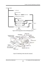
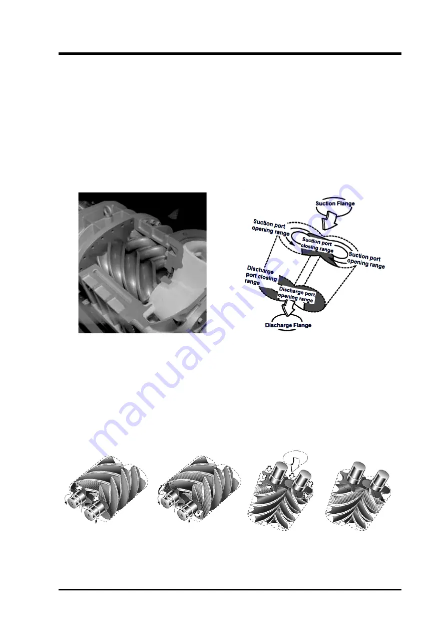
One end of each rotor constitutes the gas suction end, while the other end the compressed gas
discharge end. While the rotors are rotating over a certain angular range, their suction ends open the
suction port; the suction ends close the port while the rotors are rotating over another angular range.
This is also true with the discharge ends and the discharge port (see Figure 2-5).
Figure 2-5 Suction and Discharge Port
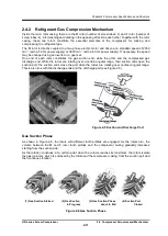
Gas Suction Phase
As shown in Figure 2-8, the rotors with different tooth profiles are engaged. As the rotors turn, the
volume between the M and F rotor tooth profiles and the compressor casing gradually increases
starting from the suction side.
As the rotation continues, at a certain point when the volume reaches its maximum, the rotors isolate
the gas (volume), which is enclosed by the rotors and the compressor casing, from the suction port and
then continues rotation.
(1) Gas Suction Started (2) Gas Suction (3) Gas Suction Phase (4) Suction Port
in Progress about to End Closed
Figure 2-6 Gas Suction Phase


