Chapter 5 Maintenance and Inspection
UD-series Screw Compressor
5.5 Reassembly
5-59
n
)
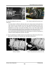
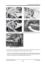
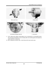
For the 400 type, the inner ring of the tilting pad has a locking key.
After inserting the tilting
pad assembly, install the key in the keyway of the inner ring, and align the tilting pad with the
stepped side of the key.
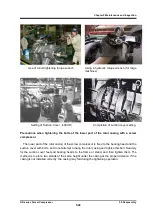
o) After attaching the lock key to the shaft, install the lock washer and lock nut, and fix the inner
ring of the tilting pad to the shaft with the lock key.
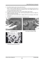
p)
A lock pin is also built into the outer ring of the tilting pad, and there is also a cutout for the lock
pin on the side of the thrust bearing gland.
Install the tilting pad while checking that the cutout
on the outer ring is aligned with the locking pin.
q)
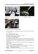
Install the spring washer and tighten the hexagon socket head cap screws (type 400 ) on the
thrust bearing gland until the specified torque is reached.
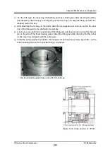
The thrust bearing gland has a cutout for the lock key.
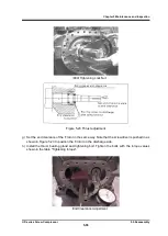
Figure 5-26 Cross section of TPTB


