background image


Chapter  7 Related Documents 

UD-series  Screw Compressor


7.1 

Assembly Sectional Views 

7-7


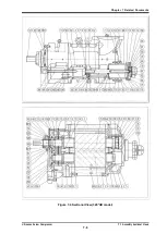
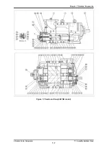
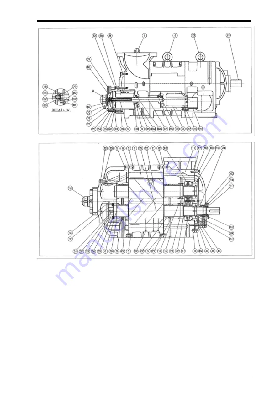
Figure 7-7 Sectional View (400*UD model) 


Содержание 125LUD

Страница 1: ...t is important to fully comprehend the contents of this manual Keep the operation manual in a safe designated place for future reference whenever the need arises Specifications of this product are sub...

Страница 2: ...60SUD 160MUD 160LUD 200SUD 200MUD 200LUD 250SUD 250MUD 250LUD 320SUD 320MUD 320LUD 400SUD 400MUD 400LUD 400LLUD 400XLUD Before installing or using this product make sure you read this manual Keep this...

Страница 3: ...h as windstorm intense rainfall flood tidal wave earthquake land subsidence thunderbolt fire etc Malfunction damage or defect to this product due to abuse or misuse such as storing this product outdoo...

Страница 4: ...ersonnel educated about the fundamentals of the product and trained about hazards involved and measures to avoid danger Do not allow any person other than those educated on the fundamental expertise o...

Страница 5: ...rs responsibility to prepare a manual for safety education and operation instructions This manual is copyrighted Drawings and technical references including this manual shall not in whole or part be c...

Страница 6: ...Maintenance and Inspection Describes sections and period for inspecting disassembly and assembly of the product 6 Troubleshooting Describes troubleshooting methods for the product in case problems occ...

Страница 7: ...anings of Warnings 1 4 1 2 2 Safety labels 1 4 1 3 Residual Risks 1 6 1 4 Safety Devices 1 9 1 4 1 Emergency Stop Button 1 9 1 4 2 Breakers for the Main Motor Power and Control Power 1 9 1 4 3 Compres...

Страница 8: ...3 Precautions for Handling lubricating Oil 4 2 4 1 4 Lubricating Oil Control Criteria 4 3 4 1 5 Lubricating Oil Replacement Timing 4 4 4 2 Precautions for Operation 4 5 4 2 1 Prevention of Liquid Flo...

Страница 9: ...over 5 52 5 5 7 Thrust Bearing Block 5 52 5 5 8 Bearing Cover 5 60 5 5 9 Unloader Piston and Unloader Cylinder 5 60 5 5 10 Unloader Cover 5 62 5 5 11 Shaft Seal Block 5 64 5 5 12 Disassembly and Assem...

Страница 10: ...f 250 UD models 7 20 Table 7 5 Parts Configuration Table of 320 UD models 7 24 Table 7 6 Parts Configuration Table of 400 UD models 7 29 7 3 Maintenance Data 7 33 7 4 Lock Nuts 7 35 7 5 Thrust Bearing...

Страница 11: ...Data Sheets SDS and strictly follow the mentioned instructions When stopping the compressor for a long time turn OFF the main motor heater and control power Close the suction and discharge side shut o...

Страница 12: ...control power It is assumed that workers only turn off main motor and control power and do not lockout tagout the main motor and control power because they think it is not important Upon completion o...

Страница 13: ...oor immediately wipe it off to prevent workers from injury caused by slipping 1 1 2 Prohibitions Don ts Do not remove or relocate any safety devices including electrical interfaces Do not disable any...

Страница 14: ...if not avoided will result in serious injury or death Indicates a potential hazardous situation which if not avoided could result in serious injury or death Indicates a potential hazardous situation...

Страница 15: ...Chapter 1 Safety UD series Screw Compressors 1 2 Warnings 1 5 Types of Safety Labels Table 1 2 Safety Label No Safety label Remarks 1 2...

Страница 16: ...us substances caused by leaking refrigerant etc 3 Avoid contact Wear protective gear Gas leakage detection Wear protective gear Work under normal temperature D Compressor discharge casing Burn caused...

Страница 17: ...parts I Oil drains from compressor unit Contact with hazard ous substances caused by leakage and blow off Burn caused by contacting with high temperature fluid Sufficient ventilation 7 Avoid contact...

Страница 18: ...Chapter 1 Safety UD series Screw Compressors 1 3 Residual Risks 1 8 Figure 1 1 Hazardous Sources Compressor V D type i e discharge port facing sideways Figure 1 2 Hazardous Sources Compressor V D type...

Страница 19: ...ons The emergency stop buttons should be installed in the controller on the compressor and in the operating control room Stop Reset Methods To activate and reset the emergency stop buttons refer to th...

Страница 20: ...function stops the compressor when oil supply is not sufficient the oil filter is clogged too much refrigerant in oil or oil supply pressure difference from suction pressure is below the set value Thi...

Страница 21: ...For inspection methods and periods please consult the package instruction manual Adjust and fine tune the set values of all safety protection devices controllers and sensors during the commissioning...

Страница 22: ...cification With these features the UD series compressor is providing a high versatility that can satisfy a wide range of operation conditions required by different applications at the load side High R...

Страница 23: ...D M E 1 Working fluid NH3 R134a R404A R507A Propane propylene CO2 R407C R407F R410A 2 Rotor diameter Symbol 125 160 200 250 320 400 3 Rotor length Symbol L D Remarks S 1 10 M 1 38 No setting for rotor...

Страница 24: ...ols First letter Slide valve second letter Bearing head port 7 Booster specifications Symbol Specification No symbol Standard B Booster specifications 1 The notation for no symbol is left justified 8...

Страница 25: ...75 2950 min 1 m3 h 295 197 622 519 415 1210 1020 810 Table 2 2 UD Series 250 Items 2 5 0 3 2 0 L U D M UD S U D L L UD L U D M UD S U D Capacity control actual load 10 100 Direction of rotation CCW se...

Страница 26: ...temperature C 60 Minimum oil supply temperature C 30 Maximum M rotor rotation speed min 1 4500 320 UD 400 UD are 3600 Minimum M rotor rotation speed min 1 1450 Applications NH3 R134a R404A R507A Prop...

Страница 27: ...long time except when starting up the machine abnormal noises or vibration may be generated So avoid such operation Repeated startup and stop in a short period is harmful not for the startup devices a...

Страница 28: ...MUD 337 325 160LUD 359 370 200SUD 337 40 5 363 407 18 300 5 260 460 4 5 30 200MUD 367 420 200LUD 393 475 250SUD 397 80 5 430 470 10 366 5 320 580 5 40 250MUD 432 502 250LUD 472 570 320SUD 443 45 0 576...

Страница 29: ...125LUD 160SUD 460 188 100 75 225 45 0 011 0 005 8 40 5 64 12 0 027 0 160MUD 160LUD 200SUD 560 225 110 90 280 55 0 012 0 007 100 50 80 15 0 027 0 200MUD 200LUD 250SUD 700 280 110 100 335 67 0 012 0 00...

Страница 30: ...355 160MUD 360 400 160LUD 400 440 200SUD 600 660 200MUD 650 720 200LUD 700 770 250SUD 1060 1170 250MUD 1140 1260 250LUD 1200 1320 320SUD 2030 2240 320MUD 2250 2480 320LUD 2400 2640 320LLUD 3110 3430...

Страница 31: ...meshing rotors called the male M and female F rotors in the casing The rotors are different in lead and number of screw lobes The volume of the sealed cavity gets reduced as the rotors rotate The gas...

Страница 32: ...s suction end while the other end the compressed gas discharge end While the rotors are rotating over a certain angular range their suction ends open the suction port the suction ends close the port w...

Страница 33: ...es and grooves decreases while the sealing line moves toward the discharge side which compresses the trapped refrigerant gas Figure 2 7 Compression Phase Discharge Phase The volume between the rotor l...

Страница 34: ...o which the volume of the sucked refrigerant gas is to be reduced In other words the compression capacity control applied to the screw compressor is a volumetric ratio control This volumetric ratio is...

Страница 35: ...re the discharge port opens as shown in the lower right graph of Figure 2 13 in next page This means that power will be used wastefully for unneeded compression Conversely if the same compressor is us...

Страница 36: ...Chapter 2 Compressor Specifications and Structure UD series Screw Compressor 2 4 Compressor Structure and Mechanism 2 15 Figure 2 12 Refrigeration Capacity of Screw Compressor...

Страница 37: ...Chapter 2 Compressor Specifications and Structure UD series Screw Compressor 2 4 Compressor Structure and Mechanism 2 16 Figure 2 13 Proper and Improper Adaptation of Vi to Load Condition...

Страница 38: ...Bellow Single Seal which is currently used as standard seal employs a stationary ring mating ring made of special cast steel a rotating ring made from carbon and O rings for the packing 2 4 6 Capacit...

Страница 39: ...2 14 Oil Supply Route of Forced Oil Supply System Figure 2 15 Lubricating oil flow inside the compressor Oil injection Unloader Push Rod Oil supply pipe for lubrication Thrust Bearing Mechanical Seal...

Страница 40: ...Chapter 2 Compressor Specifications and Structure UD series Screw Compressor 2 4 Compressor Structure and Mechanism 2 19 Figure 2 16 Oil Supply Route...

Страница 41: ...ively and fully understand their contents Electrical works should be performed only by electrical engineers 3 2 Installation Works 3 2 1 Unpacking Confirm whether a compressor does not have abnormalit...

Страница 42: ...out or hand signals are completely understood by the workers at site 9 Slowly wind up the wire ropes until immediately before the compressor leaves the ground 10 Then wind up the wire ropes a little f...

Страница 43: ...010 No Item Rotor diameter 125 160 200 250 320 1 Connecting port for liquid injection1 MYK 10A MYK 20A MYK 25A MYK 32A MYK 50A 2 Connecting port for liquid injection2 Rc 1 4 Rc 3 8 Rc 1 2 Rc 1 2 Rc 3...

Страница 44: ...1 75 18 32A 98 4 5 60 95 4 M12 P1 75 18 40A 108 4 5 68 108 4 M12 P1 75 22 50A 120 4 5 84 116 4 M16 P2 24 65CD 144 4 5 85 144 4 M16 P2 27 80A 160 4 5 119 158 4 M20 P2 5 30 100A 192 4 5 144 190 4 M22 P2...

Страница 45: ...SI 300 4 ANSI 300 5 ANSI 300 6 ANSI 300 10 ANSI 300 14 6 Lubricating oil main supply port journal NPT 3 8 ANSI 300 1 2 ANSI 300 3 4 ANSI 300 1 ANSI 300 1 1 2 7 Economizer connecting port ANSI 300 1 1...

Страница 46: ...ing oil main supply port Side Balance piston ANSI 300 2 3 Lubricating oil main supply port TPTB ANSI 300 2 4 Discharge gas outlet ANSI 300 12 5 Unloader control Decrease NPT 3 4 6 Suction gas inlet AN...

Страница 47: ...e of turning ON OFF each electric power breaker make sure to prevent electric shock For shaft alignment work between the compressor and driving machine use designated tools in normal condition If a wo...

Страница 48: ...he Compressor Oil Filter According to the requirements of the use of the package unit or the standard to apply install an oil filter of appropriate filtration precision in the lubrication system of th...

Страница 49: ...ng condition specify the procedure method and amount of the initial charge of lubricating oil and make sure to provide users of this product with such information In determining the procedure and work...

Страница 50: ...ating oil significantly changes depending on the type of the refrigerant used in combination with the oil If the refrigerant dissolves in the oil or the oil and refrigerant are compatible the viscosit...

Страница 51: ...the same manufacturer There is no problem in changing the viscosity level within the same brand However make sure that the viscosity grade will not cause problems during operation Example SUNISO 3GS...

Страница 52: ...yalphaolefine PAO 4 Synthetic oils Polyolesters POE Oil sampling and analysis is recommended every six months If the following control criteria are not satisfied replace the oil Note that the water co...

Страница 53: ...tion As the oil can easily be contaminated and degraded relatively quickly during the initial operation due to scales and deposits remaining in piping and vessels be sure to sample and analyze the oil...

Страница 54: ...the vacuum pumping performed upon initial installation or maintenance is insufficient or the suction pressure is lower than the atmospheric pressure to suck air if the suction pipe had a leak non con...

Страница 55: ...following checks every month Operate the oil pump for 10 seconds per week After that rotate the compressor shaft 10 rotations or more Measure the system pressure once per month Check for refrigerant l...

Страница 56: ...n using lifting devices e g a crane etc and or lifting tools ensure that they can sufficiently withstand the load When lifting a heavy load object do not allow anyone s body to put under it The work t...

Страница 57: ...red with oil increases the risk of slip and fall leading to an injury Also during the service there is a risk of foreign matters intruding inside the compressor to cause its damage Parts are slippery...

Страница 58: ...temperature equivalent pressure Contamination in the evaporator Temperature flow rate etc of the object to be cooled Discharge pressure MPa Difference from cooling water temperature equivalent conden...

Страница 59: ...on inspect the suction strainer Also remove the temporary filter suction cloth bag if it was supplied with the package At the beginning of operation or just after the periodical maintenance the differ...

Страница 60: ...nt criteria provided in 4 1 4 Management of Lubricant in this manual replace oil Analyze lubricant at intervals of 6 months Oil filter Replace annually Replace the filter element if the pressure diffe...

Страница 61: ...ions and Overhaul Frequency Guidelines Application Recommended Overhaul Frequency Remarks Cold storage and refrigeraion 40 000 hours or 5 years Relatively stable operating condition Ice maker Chiller...

Страница 62: ...ons given in Chapter 3 Section 3 1 General Installation Precautions and Section 3 2 3 Transportation of this manual Carefully read this manual and fully understand the details before starting to work...

Страница 63: ...1 9 O ring Suction Cover 1 1 1 1 1 1 12 Gasket Bearing Head 1 1 1 1 1 1 17 Bearing Cover Gasket 1 1 1 1 1 1 23 Gasket Balance Piston Cover 1 1 1 1 1 1 27 Main Bearing with O ring 2 2 2 2 2 2 28 Side B...

Страница 64: ...ced if any abnormality is found 1 1 1 1 1 1 150 O ring Thrust Bearing Gland 320 for 320V D 2 2 216 Gasket Lubricating Oil Inlet Flange Journal inlet 1 1 1 1 219 Gasket Oil Injection Inlet Flange for 3...

Страница 65: ...iently share the work details among all the coworkers through checking and confirmation before actually starting the work Before the work be sure to check and communicate the work details and procedur...

Страница 66: ...e bearing of compressor F rotor side 6 Liquid injection Aquamizer 1 piping to the compressor 7 Liquid injection Aquamizer 2 piping to the compressor 8 Economizer Electromizer piping to the compressor...

Страница 67: ...the suction cover on the workbench and place the leg part of bearing head on the temporally stand as shown in Figure 5 1 a Place the compressor on the special stand or use a temporary stand as shown i...

Страница 68: ...ple and the actual order may differ according to individual situations Depending on the situation please complete the work in a safe and appropriate procedure a Unloader indicator block n some cases t...

Страница 69: ...0 to 100 by using a potentiometer and contact output function by using micro switches Major changes improvements are described in Table 5 6 Table 5 6 Difference of Unloader Indicator between old type...

Страница 70: ...nd after removing the wires attach the cover to them for protection a By removing the three hexagon socket head cap screws 147 that are used to fasten the indicator cover 146 the cover can be removed...

Страница 71: ...ometer 129 micro switches 125 and micro switch cam 127 can be removed b Unscrew and remove three hexagon socket head cap screws 122 c Loosen the set screw 128 of the micro switch cam d After that the...

Страница 72: ...remove six bolts leaving two diagonally opposite bolts b Loosen the remaining two screws alternately and evenly a little at a time When the screws are loosened to some extent the seal cover will be pu...

Страница 73: ...n the set screw of the seal collar Inspection a Although it is instructed that the mechanical seal must be replaced after abnormality is found in the inspection only visually checking the sliding surf...

Страница 74: ...ly and assembly work of these mechanical seals a qualified trained personnel and special tools are required For details contact us Disassembly After removing the hexagon socket head cap screws 53 and...

Страница 75: ...to the axis of the push rod in the unloader cylinder Carefully pull it straight because if the unloader cover is pulled sideways the shaft of the indicator cam may be bent c If the indicator cam will...

Страница 76: ...cator Cam Unloader Cover Inspection a Check the packing of the indicator cam shaft for any flaw If the refrigerant leaks without any flaw observed in this part it should be due to a defect of the V ri...

Страница 77: ...Chapter 5 Maintenance and Inspection UD series Screw Compressor 5 4 Disassembly and Inspection 5 22 Figure 5 8 Unloader Cover Block 125 320 Type Figure 5 9 Unloader Cover Block 400 Type...

Страница 78: ...the unloader piston out of the push rod Bend back the claw lock washer for locking Figure 5 10 Remove Unloader Piston d The unloader cylinder is assembled to the balance piston cover with two short h...

Страница 79: ...rod Inspection of cap seal Unloader Push Rod O Ring 5 4 6 Removal of Bearing Cover If it is less than 320 the discharge flange is in an asymmetrical position so the left and right balance is poor in t...

Страница 80: ...the rotor end face and the bearing head discharge end face Disassembly a Among the bolts Part No 18 1 and 18 2 tightening the bearing cover replace the two bolts at the upper position without head saf...

Страница 81: ...or 5 4 Disassembly and Inspection 5 26 Thrust bearing 1 set Figure 5 11 Conical Spring Washer Figure 5 12 Development view of the 125 250 thrust bearing 250 does not have thrust bearing outer race spa...

Страница 82: ...e off at the same time Removal of Thrust Bearing Gland Removal of Thrust Bearing Gland After removing the Thrust Bearing Gland Bend back of the lock washer b Bend back of the lock washer part number 4...

Страница 83: ...nd F rotor There is a engrave indicating the rotor used If the assembly position is mistaken during reassembly the end clearance between the discharge end surface and the bearing head end surface will...

Страница 84: ...downward Make sure the inside of the combination is facing down If the rotation is not smooth and it is uneven or hooked it is caused by dust or scratchesIn that case check again and wash or replace...

Страница 85: ...d remove the lock nut and lock washer Lock nut 2 Figure 5 15 Development View of the Thrust Bearing b Remove the key on the shaft and store it in a safe place c Insert two eye bolts into the bolt hole...

Страница 86: ...4 Disassembly and Inspection 5 31 Thrust Bearing 1 Thrust Bearing 2 e Remove the thrust bearing alignment spacers from the rotor Thrust bearing alignment spacer 1 Thrust bearing alignment spacer 2 Cu...

Страница 87: ...the unloader cylinder Disassembly a Loosen all the hexagon socket head cap screws part number 24 by 3 to 4 turns screw the eyebolts into the screw holes of the balance piston cover and remove the cove...

Страница 88: ...Pull out the Balance Piston Balance piston 5 4 9 Balance Piston The screw compressor is structurally of the two rotors M and F and the M rotor rotates 1 5 times more than the F rotor because the thrus...

Страница 89: ...w to fasten the cut out part of the balance piston sleeve with a screw 160 250 type Type 2 Drive the spring pin into the sleeve and fit it into the groove of the suction cover 320 400 type Type 1 Bala...

Страница 90: ...ing spacer inside the sleeve h If you plan to remove the side bearings also remove the stop ring part number 37 inside Inspection for Balance Piston and Balance Piston Sleeve There is a mark of wear o...

Страница 91: ...and the injection pipe is attached to the outer periphery of the unloader push rod Relaying the unloader push rod and slide valve from the suction cover injection oil is supplied to the rotor meshing...

Страница 92: ...emoved bolts to the screw holes for the removal bolts on the rotor casing side and alternately screw in little by little to widen the clearance between the suction cover and rotor casing If not screwe...

Страница 93: ...is deformed or the sliding part on the outer circumference is abnormal Be sure to replace the O ring part number 73 on the unloader piston fitting b Check if foreign matter is embedded in the inner s...

Страница 94: ...ontact and outer diameter for wear or damage Abnormalities rarely occur in normal use If it is damaged foreign matter may have been sucked in The suction gas filter or the oil filter must be checked c...

Страница 95: ...g can be removed by pulling out the stop ring part number 29 from the bearing cover side of the bearing head with the stop ring pliers and pressing the main bearing If the fitting is hard do not hit t...

Страница 96: ...y a Remove the unloader slide valve assembly from the casing It is not necessary to disassembly the unloader slide valve assembly except when replacing the unloader pushrod b To replace this rod remov...

Страница 97: ...G220 2 G290 2 325 O ring retainer P70 2 432 Main Bearing G85 4 G22 4 G135 4 G165 4 G200 4 433 Side Bearing G85 4 G22 4 G135 4 G165 4 G200 4 674 Seal Cover G39 1 indicates the Q ty JIS W1516 No mark J...

Страница 98: ...figure This happens if the guide block is not installed properly In the figure B carefully checks the rotor casing and slide valve Sharpen or polish the bottom of the slide valve so that it becomes t...

Страница 99: ...on the F Rotor a First apply oil to the bearing head side shaft of the F rotor and also apply oil to the inside of the main bearing Install from F rotor to rotor casing Use a crane or chain block to h...

Страница 100: ...touches the casing Turning it can damage the edges of the robes 5 5 4 Suction Cover Side Bearing and Oil Injection Pipe a Install the side bearings in the suction cover in the same way as the main be...

Страница 101: ...e positioning pin toward the rotor casing side The gasket of the suction cover is asymmetric Check that it is properly fitted Lubricate the side bearings sufficiently For 320 type and 400 type attach...

Страница 102: ...D series Screw Compressor 5 5 Reassembly 5 47 Suction cover tightening bolts Inside of suction cover Suction Cover Gasket left right asymmetric Install Suction Cover 125 320 Fitting the unloader push...

Страница 103: ...ine the unloader push rod with the O ring retainer on the suction cover Then combine the rotor shaft and side bearings by pushing them parallel to the combined shaft core Also when assembling the roto...

Страница 104: ...tor casing with a screw compressor The lower part of the rotor casing of the screw compressor is fixed to the bearing head and the suction cover with bolts but do not attempt to hang the rotor casing...

Страница 105: ...7 Next install the O ring spacer part number 36 O ring part number 35 balance piston sleeve part number 33 and stop ring in that order Finally the stop ring to be assembled is pushed outward by the O...

Страница 106: ...ut out position with the hexagon socket set screw c Assemble the stop ring part number 37 for fixing the balance piston sleeve d Tighten the hexagon socket set screw until the head protrudes from the...

Страница 107: ...t Bearing Block a Position the thrust bearing spacer part number 41 and thrust adjusting washer part number 42 so that they are correctly on the M rotor and F rotor sides This is very important for cl...

Страница 108: ...clearance Install the Thrust Bearing Alignment spacer Bearing assembly Table 7 End clearance Unit mm Model For single stage high stage S M L LL XL 125 0 03 0 05 160 0 04 0 06 200 0 05 0 07 250 0 08 0...

Страница 109: ...For the 400 UD insert the thrust bearing key in the direction of the shaft key Install the lock washer and lock nut and tighten the lock nut using the lock nut spanner f With the inner ring of the th...

Страница 110: ...ustment g Set the end clearance of the F rotor in the same way Note that the screwdriver is pushed in as shown in Figure 5 23 to position the F rotor on the discharge side h Install the thrust bearing...

Страница 111: ...series Screw Compressor 5 5 Reassembly 5 56 Figure 5 24 End Clearance adjustment II Tightening torque Figure 5 25 Model N m Kg cm Ft lb 125 30 300 21 70 160 40 400 28 93 200 50 500 36 17 250 60 600 43...

Страница 112: ...use brass or copper shim material as it will corrode if the refrigerant is ammonia 2 If the end clearance is smaller than the specified value that is if the rotor does not turn after tightening the t...

Страница 113: ...ned Note 125 320 type 1 Use new lock washers 2 Set a torsional slip washer between the lock nut and lock washer 3 Be careful not to break the claws of the lock washer m After confirming the tightening...

Страница 114: ...lock nut and fix the inner ring of the tilting pad to the shaft with the lock key p A lock pin is also built into the outer ring of the tilting pad and there is also a cutout for the lock pin on the s...

Страница 115: ...ts on the diagonal making sure that the bearing covers are parallel After the whole surface of the bearing cover contacts the bearing head fix the remaining hexagon socket head cap screws Setting the...

Страница 116: ...and balance piston cover to the suction cover View of suction cover where unloader cylinder balance piston cover unloader piston are fitted Positioning unloader push rod on the suction cover side c Pu...

Страница 117: ...etting Lock Washer and Lock Nut Tigten the Lock Nut to the specified torque Bend the claws of the lock washer Confirm operation with eyebolts Full unloaded position push to the end 5 5 10 Unloader Cov...

Страница 118: ...ssembled in a into the V ring and tighten the ball bearing to the unloader cover with the bearing retainer d Make sure that the cylindrical cam rotates smoothly and then attach the O ring part number...

Страница 119: ...lock The assembly procedure of the shaft seal block is the reverse sequence described in Section 5 4 3 as shown in the order of the colored number of each sectional view drawing Disassembly and assemb...

Страница 120: ...system consists of a potentiometer a macro switch and a cam 1 IND 02 125 2 160 400 Type 160 400 125 type unloader indicator 160 400 type unloader indicator The 125 type components are as follows Pote...

Страница 121: ...1 Micro switch Slide valve partial load position signal for 50 load 1 1 Micro switch Slide valve partial load position signal for special specifications 2 Micro switch Cam For 0 100 operation 1 Micro...

Страница 122: ...Chapter 5 Maintenance and Inspection UD series Screw Compressor 5 5 Reassembly 5 67 Figure 5 30 Development View of the Unloader Indicator 160 400 type...

Страница 123: ...Chapter 5 Maintenance and Inspection UD series Screw Compressor 5 5 Reassembly 5 68 Figure 5 31 Sectional View of UD series Unloader Indicator Traditional standard type...

Страница 124: ...ass spacer 1 123 Micro switch setting plate 1 133 Phillips Screw 2 143 Indicator glass spacer 1 124 Phillips Screw 1 134 Dial plate support 2 2 144 Bracket 1 125 Micro switch 2 135 Dial plate support...

Страница 125: ...k the operation of the contacts of electrical parts Since the potentiometer is a full rotation type check that the resistance value changes smoothly throughout the full revolution If the surrounding e...

Страница 126: ...ioning mark 1 micro switch c Fix the dial with the indicator needle aligned to the no load position The full loadmicroswitch will eventually pneumatically move the unloader piston to the full load pos...

Страница 127: ...emove clogging Check oil contamination level and replace oil if necessary Unconfirmed cooling water circulation Malfunction in devices such as cooling water pumps and related circuits Identify malfunc...

Страница 128: ...oil filter element Big difference in outlet inlet pressures Contamination of lubricant Remove clogging Check oil contamination level and change lubricant as necessary Defect inside compressor Check oi...

Страница 129: ...ce malfunctioning devices Flow volume adjustment failure of cooling water brine etc If regulating valve is manually adjusted readjust it If an automatic control valve including wax valve is used exami...

Страница 130: ...clogging in the tubing for high pressure protection switch Remove clogging Check oil contamination level and replace oil as necessary Closed outlet stop valve for oil separator Neglected to restore af...

Страница 131: ...seal Initial leak after replacement until mating surface seal and shaft fit each other Initial wear stage of mating surface For initial leak amount of leak might increase temporarily However it will g...

Страница 132: ...iding surface can be applied Incompatibility between operating conditions working temperature ranges refrigerant etc and lubricant Inappropriate lubri cant or change in operating conditions since inst...

Страница 133: ...oint and span adjustment for E E positioner Readjust it Malfunction of E E positioner or its indicator For aging degradation replace E E positioner For unique causes such as surge current remove the c...

Страница 134: ...nd or noise of compressor Insufficient alignment between compressor shaft and motor shaft If vibration value is higher in the axial direction insufficient alignment might be the cause Realign the shaf...

Страница 135: ...auses more than one may exist and take measures Then perform an overhaul of the compressor Liquid flow back during operation Frosting on suction side is conspicuous In many cases the phenomenon is oft...

Страница 136: ...for heat exchanger on load side Shortage in heat exchanger capacity on load side due to the failure of heat exchanger Inspect for blockage of heat exchanger tubes and malfunction of fans of heat exch...

Страница 137: ...tenance interval management Faulty assembly Lock nuts tightened insufficiently lock washer tab not bended etc Tighten lock nuts by using specified torque Be sure to record data on the assembly check s...

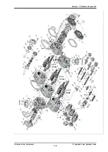
Страница 138: ...Chapter 7 Related Documents UD series Screw Compressor 7 1 Exploded Views Sectional Views 7 1 Chapter 7 Related Documents 7 1 Exploded Views Sectional Views Figure 7 1 Exploded View 125 UD model...

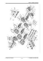
Страница 139: ...Chapter 7 Related Documents UD series Screw Compressor 7 1 Exploded Views Sectional Views 7 2 Figure 7 2 Exploded View 160 250 UD model...

Страница 140: ...Chapter 7 Related Documents UD series Screw Compressor 7 1 Exploded Views Sectional Views 7 3 Figure 7 3 Exploded View 320 UD model...

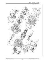
Страница 141: ...Chapter 7 Related Documents UD series Screw Compressor 7 1 Exploded Views Sectional Views 7 4 Figure 7 4 Exploded View 400 UD model...

Страница 142: ...Chapter 7 Related Documents UD series Screw Compressor 7 1 Assembly Sectional Views 7 5 Figure 7 5 Sectional View 125 to 250 UD model...

Страница 143: ...Chapter 7 Related Documents UD series Screw Compressor 7 1 Assembly Sectional Views 7 6 Figure 7 6 Sectional View 320 UD model...

Страница 144: ...Chapter 7 Related Documents UD series Screw Compressor 7 1 Assembly Sectional Views 7 7 Figure 7 7 Sectional View 400 UD model...

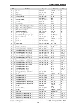
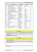
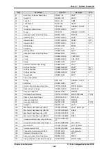
Страница 145: ...E3204 010 4 10 2 16 Bearing Cover CS01600 125D 125 1 UD 17 Gasket Bearing Cover CS01700 125DN 125 1 UD 18 1 Hexagon Socket Head Cap Screw NB35412 030 M12 30 13 UD 18 2 Hexagon Socket Head Cap Screw NB...

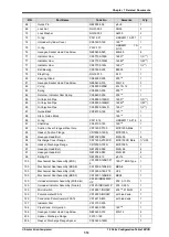
Страница 146: ...Cylinder CS06000 125L 125 1 61 Hexagon Socket Head Cap Screw NB35408 025 M8 25 2 62 Hexagon Socket Head Cap Screw NB35408 065 M8 65 6 63 O ring PA12 095 JISB2401 1A G95 1 64 Unloader Piston CS06400 1...

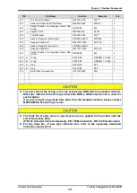
Страница 147: ...1 IND0203 125 1612 shared right 1 127 Micro Switch Cam CS12700 125F 125 0 100 1 127 Micro Switch Cam CS12700 125H 125 0 50 1 129 Potentiometer CS1299 E10 200 1K with lead wire 1 129 Conductive Potenti...

Страница 148: ...t part code is used for each material If you are using O rings made from other than the standard material please contact MAYEKAWA when placing an order The Code No of parts shown in parentheses below...

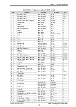
Страница 149: ...2 15 Plug NF06 008 R1 4 1 16 Bearing Cover CS01600 160D 160 1 UD 17 Gasket Bearing Cover CS01700 160DN 160 1 UD 18 1 Hexagon Socket Head Cap Screw NB35412 040 M12 40 17 UD 18 2 Hexagon Socket Head Cap...

Страница 150: ...S 54 M Unloader Slide Valve 1 M Port CS05400 160SDM 160S 1 S 54 H Unloader Slide Valve 1 H Port CS05400 160SDH 160S 1 S 54 L Unloader Slide Valve 1 L Port CS05400 160MDL 160M 1 M 54 M Unloader Slide V...

Страница 151: ...B2401 1A P16 2 91 Shaft Key CS09100 160 160 1 92 Suction Cover Flange without hole CS71400 P125 MYK125A Male 1 93 Gasket Suction Flange CR72000 125N MYK125A 1 94 Hexagon Head Bolt NB12020 055 M20 55 8...

Страница 152: ...ad Cap Screw ND330 08 M8 4 432 A O ring PA12 085 JISB2401 1A G85 4 433 B O ring PA12 085 JISB2401 1A G85 4 605 A Plug NF06 015 R1 2 1 607 B Plug NF06 004 R1 8 1 715 Blind Plate for Aquamizer CS71500 0...

Страница 153: ...00 12 M12 1 14 Spring Pin NE3206 012 6x12 2 16 Bearing Cover CS01600 200D 200 1 UD 17 Gasket Bearing Cover CS01700 200DN 200 1 UD 18 1 Hexagon Socket Head Cap Screw NB35416 050 M16X50 17 UD 18 2 Hexag...

Страница 154: ...54 L Unloader Slide Valve L Port CS05400 200SDL 200S 1 S 54 M Unloader Slide Valve M Port CS05400 200SDM 200S 1 S 54 H Unloader Slide Valve H Port CS05400 200SDH 200S 1 S 54 L Unloader Slide Valve L P...

Страница 155: ...k CS08700 200 200 1 88 Stem Guide Block 89 O ring PA11 020 JISB2401 1A P20 2 91 Shaft Key CS09100 200 200 1 92 Suction Cover Flange without hole CS71400 P150 MYK150A 6 Male 1 93 Gasket Suction Flange...

Страница 156: ...0 M10 4 432 O ring PA62 022 JIS W1516 1A G22 4 433 O ring PA62 022 JIS W1516 1A G22 4 528 Sleeve Oil Seal CS52809 200VD 200V 1 529 A Set Screw NA83606 008 M6X8 2 605 B Plug NF06 020 R3 4 1 607 A Plug...

Страница 157: ...ng Head CS01200 250N 250 1 13 Eye Bolt NB600 12 M12 1 14 Spring Pin NE3206 012 6x12 2 16 Bearing Cover CS01600 250D 250 1 UD 17 Gasket Bearing Cover CS01700 250DN 250 1 UD 18 1 Hexagon Socket Head Cap...

Страница 158: ...5412 030 M12X30 8 54 M Unloader Slide Valve L Port CS05400 250SDL 250S 1 S 54 H Unloader Slide Valve M Port CS05400 250SDM 250S 1 S 54 L Unloader Slide Valve H Port CS05400 250SDH 250S 1 S 54 M Unload...

Страница 159: ...Guide Block CS08700 250 250 1 88 Stem Guide Block 89 O ring PA11 020 JISB2401 1A P20 2 91 Shaft Key CS09100 250 250 1 92 Suction Cover Flange without hole CS71400 P250 MYK250A Male 1 93 Gasket Suction...

Страница 160: ...32N MYK32A 1 256 A Hexagon Head Bolt NB111012 040 M12X40 4 267 B Spring Washer fro Hexagon Head Cap Screw ND330 12 M12 4 432 A O ring PA12 130 JISB2401 1A G130 4 433 B O ring PA12 130 JISB2401 1A G130...

Страница 161: ...Head CS01100 320DM 320 1 UD 11 L Bearing Head CS01100 320DL 320 1 UD 12 Gasket Bearing Head CS01200 320N 320 1 13 Eye Bolt NB600 16 M16 1 Plain Washer Eye Bolt ND710 016 M16 30 2 14 Spring Pin NE3206...

Страница 162: ...UV4 1 51 L Seal Cover CS05100 320HE 320 HE 52 M Gasket Seal Cover CS05200 320N 320 1 53 H Hexagon Socket Head Cap Screw NB35416 040 M16X40 8 54 5 5 L Unloader Slide Valve Assembly L Port CS05400 320SD...

Страница 163: ...AN10 1 70 Lock Washer NG32 010 AW10 1 71 Lock Nut NG31 012 AN12 1 72 Lock Washer NG32 012 AW12 1 73 O ring PA11 044 JISB2401 1A P44 1 74 Unloader Cylinder Cover CS07400 320 320 1 75 O ring PA12 210 J...

Страница 164: ...nge Lubrication Oil Supply CS71400 040 MYK40A 1 1 2 Male 1 216 Gasket Lubrication Oil Supply Flange CR72000 040N MYK40A 1 217 Hexagon Head Bolt NB15512 040 M12X40 4 218 Flange Injection Oil Supply CR7...

Страница 165: ...t part code is used for each material If you are using O rings made from other than the standard material please contact MAYEKAWA when placing an order The Code No of parts shown in parentheses below...

Страница 166: ...olt NB600 42 M42 1 14 Spring Pin NE3208 025 8 25 2 15 A Plug NF062 N008 NPT 1 1 15 B Plug NF062 N010 NPT 1 1 4 1 15 C Plug NF062 N006 NPT 3 4 1 16 Bearing Cover CS01607 400D 400 UD 1 17 Gasket Bearing...

Страница 167: ...0S 1 SUD 54 Unloader Slide Valve L Port CS05400 400MDL 400M 1 MUD 54 Unloader Slide Valve M Port CS05400 400MDM 400M 1 MUD 54 Unloader Slide Valve L Port CS05400 400LDL 400L 1 LUD 54 Unloader Slide Va...

Страница 168: ...NCU1511 4 7UNC 1 1 4 7UNC 20 96 Gasket Discharge Flange PL300 300 ANSI 300 12 1 97 Stud Bolt Nut NBU611 8 7UNC 1 1 8 7UNC X 150mm 16 NCU1511 8 7UNC 1 1 8 7UC 16 100 Mechanical Seal Assembly CS10000 4...

Страница 169: ...Washer Hexagon Socket Head Cap Screw ND330 16 M16 7 325 O ring PA11 070 JISB2401 1A P70 2 326 Gland O ring CS32600 400 400V 1 346 Key Thrust Bearing TP CS34600 400 400 2 432 O ring PA12 200 JISB2401 1...

Страница 170: ...Chapter 7 Related Documents UD series Screw Compressor 7 2 Parts Configuration Table 400 UD 7 33...

Страница 171: ...Size N m kgf cm 125 M8 25 30 300 160 M10 30 40 400 200 M12 35 50 500 250 M16 45 60 600 320 M20 55 120 1200 400 M20 75 90 900 Model For single stage high stage S M L LL XL 125 0 03 0 05 160 0 04 0 06...

Страница 172: ...259 22 590 2 824 28 240 Table 7 12 Retaining Ring Location 125 160 200 250 320 400 29 Main Bearing CE IN80 H80 2 CE IN102 H102 2 CE IN130 H130 2 CE IN160 H160 2 CE IN200 H200 2 CE IN250 H250 2 29 Side...

Страница 173: ...until the rotor turns c Use a lock nut wrench and a hammer hit twice lightly d Use a lock nut wrench and a hammer loosen the lock nut Tightening Angle Range of Lock Nuts for Rotors a After tightening...

Страница 174: ...0 320 400 4 M10 4 M12 4 M16 4 M20 6 M20 1 First tighten all bolts by hand 0 0 0 0 0 0 2 Next temporarily tighten diagonally and uniformly with a snug torque 25 x specified torque 25 10 13 15 30 23 3 N...

Страница 175: ...2 P42 2 G55 2 G60 2 P58 1 G95 1 35 Balance Piston Sleeve G95 1 P120 1 P150 1 G190 1 G240 1 49 Seal Retainer G85 1 G90 1 G115 1 G135 1 G160 1 G160 1 59 Oil Injection Pipe P30 2 P30 2 P40 2 P46 2 P32 1...

Страница 176: ...5 380 463 G Downward discharge W 388 480 580 23 Balance Piston Cover H 270 333 340 517 W 283 350 420 532 52 Seal Cover 140 170 200 250 93 Suction Flange 173 125A 198 150A 325 250A 421 350A 96 Discharg...

Страница 177: ...Flat blade 75 mm SG111 075 125 mm SG111 125 Snap ring pliers External ST 1 SG311 01 ST 2N SG311 02N ST 3 SG311 03 Snap ring pliers Internal RT 4 SG312 04 RT 5 Eye bolt M8 200 two peace set UHT0016 Al...

Страница 178: ...r Disassembly 7 41 Tool name Illustration size etc Code No AN 21 SAS111 21 Torque wrench for assembly 5 25 N m 20 100 N m SG132 0900 60 420 N m SG132 4200 Assembly and Disassembly Tool Main Side Beari...

Страница 179: ...MAYEKAWA MFG CO LTD 3 14 15 Botan Koto ku Tokyo 135 8482 JAPAN Phone 81 0 3 3642 8181 URL http www mayekawa com...

Отзывы: