Chapter 5 Maintenance and Inspection
UD-series Screw Compressor
5.5 Reassembly
5-52
5.5.6
Balance Piston Cover
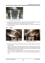
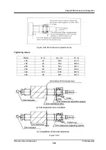
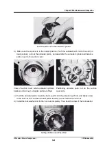
Balance piston cover and unloader cylinder
When reassembling, if the balance piston cover and unloader cylinder are joined in advance and
then attached to the suction cover, the unloader push rod and unloader piston can be easily
adjusted. Remember to attach the "O" ring (part number 63).
(See unloader piston and unloader
cylinder section).
This part is only a cover, so there is no failure.
5.5.7
Thrust Bearing Block
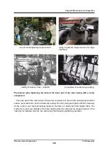
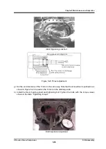
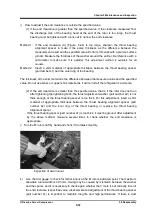
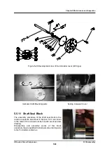
a) Position the thrust bearing spacer (part number 41) and thrust adjusting washer (part number
42) so that they are correctly on the M rotor and F rotor sides.
This is very important for
clearance on the rotor discharge side. (See Figure. 5-23)
b) Keep the gap between the thrust bearing spacer and the thrust adjusting washer clean.
Residues and dust affect the end clearance.
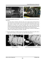
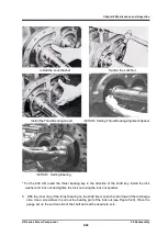
c) Position the thrust bearing so that the apex of the V stamped on the bearing is on the rotor
side.
d)
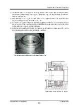
Then attach the lock washer (part number 40), tighten the lock nut for the bearing (part number
39), and fix the inner ring to the thrust bearing on the shaft.
V mark on thrust bearing Figure 5-22 Adjustment of thrust bearing


