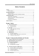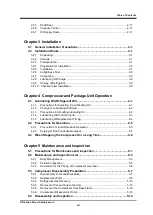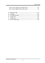
Table of Contents
UD-series Screw Compressors
viii
5.4.1
Unloader Indicator Block ................................................................................... 5-14
5.4.2
Shaft Seal Block................................................................................................ 5-17
5.4.3
Shaft Seal ......................................................................................................... 5-19
5.4.4
Unloader Cover ................................................................................................. 5-20
5.4.5
Unloader Piston and Unloader Cylinder ........................................................... 5-23
5.4.6
Removal of Bearing Cover ................................................................................ 5-24
5.4.7
Thrust Bearings................................................................................................. 5-25
5.4.8
Balance Piston Cover ....................................................................................... 5-32
5.4.9
Balance Piston .................................................................................................. 5-33
5.4.10 Oil Injection Pipe ............................................................................................... 5-36
5.4.11 Suction Cover and Side Bearing....................................................................... 5-37
5.4.12 Rotor and Rotor Casing .................................................................................... 5-38
5.4.13 Bearing Head and Main Bearing....................................................................... 5-40
5.4.14 Unloader Slide Valve and Guide Block ............................................................. 5-41
5.5 Reassembly .............................................................................................. 5-42
5.5.1
Unloader Slide Valve and Guide Block(125-320) ............................................. 5-42
5.5.2
Bearing Head and Main Bearing....................................................................... 5-43
5.5.3
Rotor ................................................................................................................. 5-44
5.5.4
Suction Cover, Side Bearing and Oil Injection Pipe ....................................... 5-45
5.5.5
Balance Piston Sleeve ...................................................................................... 5-50
5.5.6
Balance Piston Cover ....................................................................................... 5-52
5.5.7
Thrust Bearing Block ........................................................................................ 5-52
5.5.8
Bearing Cover ................................................................................................... 5-60
5.5.9
Unloader Piston and Unloader Cylinder ........................................................... 5-60
5.5.10 Unloader Cover ................................................................................................. 5-62
5.5.11 Shaft Seal Block................................................................................................ 5-64
5.5.12 Disassembly and Assembly of the unloader Indicator ...................................... 5-65
Chapter 6 Troubleshooting
01: Compressor does not start up.................................................................................... 6-1
02: Compressor stops immediately after startup ............................................................. 6-1
03: Abnormally low pressure ............................................................................................ 6-2
04: Low oil-supply pressure ............................................................................................. 6-2
05: Abnormal high pressure. ............................................................................................ 6-3
06: Abnormally high discharge temperature .................................................................... 6-4
07: Leak from mechanical seal ........................................................................................ 6-5
08: Squeaking sound from mechanical seal part ............................................................. 6-6
09: Faulty indication of capacity control position ............................................................. 6-7
10: Capacity control malfunction ...................................................................................... 6-7
11: Abnormal vibration and/or noise of compressor ........................................................ 6-8
Chapter 7 Related Documents
7.1 Exploded Views, Sectional Views ............................................................. 7-1
7.2 Parts Configuration Table .......................................................................... 7-8
Table 7-1 Parts Configuration Table of 125*UD models ................................................. 7-8
Table 7-2 Parts Configuration Table of 160*UD models ............................................... 7-12
Table 7-3 Parts Configuration Table of 200*UD models ............................................... 7-16

