Chapter 5 Maintenance and Inspection
UD-series Screw Compressor
5.5 Reassembly
5-65
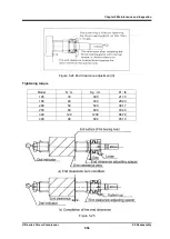
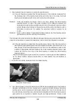
Note that to confirm the sliding surface pressure of the mechanical seal is proper or not, measure
the clearance between the surfaces of the seal cover gasket and the bearing cover flange. This
clearance is called " fastening margin of the seal", it should be measured by using a taper gauge.
The proper value guide line (reference) of this " fastening margin of the seal" is; 3 mm as BOD
type seal, 5 mm as BBD
Ⅱ
type seal, and 6 mm as BBDE type seal.
5.5.12 Disassembly and Assembly of the Unloader Indicator
The indicator of the automatic control system consists of a potentiometer, a macro switch and a
cam.
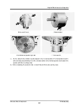
(1) IND-02
125
***
(2) 160
~
400 Type
160
***~
400
***
125 type unloader indicator
160-400 type unloader indicator
The 125 type components are as follows
Potentiometer
For feedback of slide valve position
Micro-switch
For slide valve no-load (0 %) position signal
Micro-switch
For signals at slide valve full load (100 %)
position
Cam
For micro-switch
The components of 160-400 type and above are as follows
The numbers in the table below indicate the number of pieces, and (1) indicates that one of them
should be used.
Parts
Automatic
standard
operation
Special
specifications
(1)
Special
specifications
(2)
Special
specifications (3)
3 micro switches
specifications
Potentiometer
(
For feedback of slide valve
position
)
1
1
1
1
Micro-switch
(
For slide valve no-load (0 %)
position signal
)
1
1
1
1

