Chapter 5 Maintenance and Inspection
UD-series Screw Compressor
5.4 Disassembly and Inspection
5-37
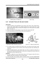
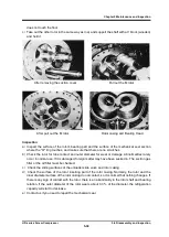
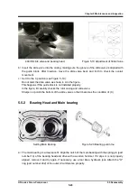
c) The oil injection pipe retainer and the oil injection pipe (part number 85) are connected by
spring pins so they can be pulled out at the same time.
Oil injection pipe retainer
Oil hole for oil injection
Inspection
a)
Replace the "O" ring.
It is installed in two places inside the oil injection pipe.
b)
Also replace the “O” ring (part number 9) which is in the hole for the oil injection pipe in the
center of the suction cover.
(
Arrow indication
)
5.4.11 Suction Cover and Side Bearing
Disassembly
a
)
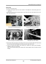
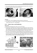
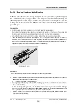
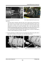
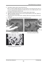
Remove all bolts that attach the suction cover to the rotor casing.
b
)
Tighten the two removed bolts to the screw holes for the removal bolts on the rotor casing side,
and alternately screw in little by little to widen the clearance between the suction cover and
rotor casing.
If not screwed evenly, the positioning pin will be bent.
Remove the gasket when
there is a small gap.
At this time, remove the gasket so that it is on the suction cover side.
c
)
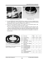
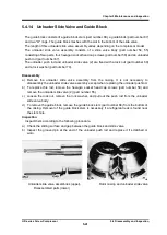
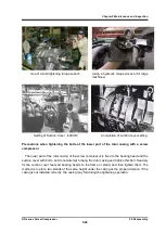
Then screw in the bolts alternately to widen the gap and remove the positioning pin. Then, lift
the suction cover with a crane to separate the rotor shaft and unloader pushrod assembled on
the suction cover side from the suction cover.
Slide it parallel to the rotor axis on the work
bench to separate it from the rotor casing. Move the suction cover while pushing the rotor back
into the rotor casing so that the rotor does not fall out at this time.
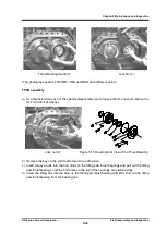
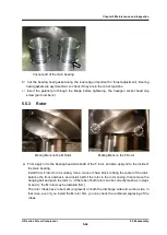
Figure 5-18 Removal of Suction cover
Removal of Suction cover (400UD)

