Chapter 5 Maintenance and Inspection
UD-series Screw Compressor
5.5 Reassembly
5-48
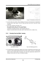
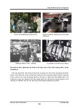
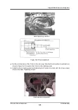
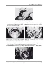
For large models, it is difficult to slide the suction cover on the work bench during the above
work, so place the rotor casing side on the end of the work table and hang the suction cover
with a crane to combine.
In such a case, use a chain block or the like so that the vertical
adjustment can be made.
For the 320 and 400 tys, slide on the surface plate and first
combine the unloader push rod with the "O" ring retainer on the suction cover.
Then combine
the rotor shaft and side bearings by pushing them parallel to the combined shaft core.
Also, when assembling the rotor bearings on the side bearings, be careful not to damage the
inside of the side bearings at the end of the rotor shaft.
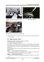
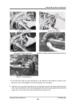
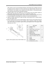
g) Drive the positioning pin.
Tighten the bolt to the specified torque.
When the tip of the rotor is
aligned with the bearing, move it parallel to the rotor shaft and assemble it.
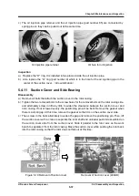
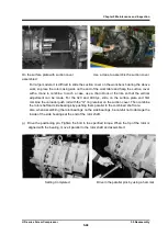
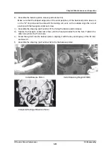
On the surface plate with suction cover
assembled
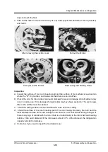
Use a crane to assemble the suction cover
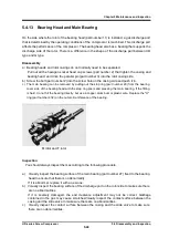
Setting Completed
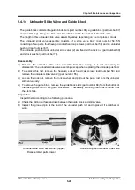
Drive in the parallel pins by using a hammar


