11 Appendix
Maschinenfabrik Reinhausen GmbH 2016
217
5163667/00 EN
TRAFOGUARD® ISM®
Appendix
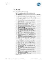
Check list for commissioning
Observe the following check list to perform commissioning:
No.
Description
Complete
1
Cap rail corresponds to standard EN 60715 type TH
35-7.5 or TH 35-15 and is mounted horizontally.
2
The distance of the screws for fastening the cap rail is
a maximum of 10 cm.
3
The assemblies have been mounted correctly on the
cap rail and locked in. The assemblies are sitting firm-
ly on the cap rail.
4
The device has been installed correctly and the mini-
mum distances [
5
The dimensions of the supply line are in accordance
with the performance data on the nameplate.
6
The supply line is fused with a miniature circuit break-
er of type C6A or B6A.
7
The 24 V supply cables are connected using a termi-
nal strip that is located near the power supply.
8
The cable cross-section of the 24 V voltage supply is
1.5 mm²
9
The 24 V supply cables are not longer than 2.5 m
10
The 24 V supply is, in accordance with the connection
diagram, connected exclusively with the assembly of
this device.
11
Voltage transformers and current transformers are de-
signed for connection to the inputs for voltage meas-
urement and current measurement (see technical da-
ta [
12
The DIO assembly is connected correctly to the CPU
assembly using the
provided
CAN bus cable. For
CAN bus cables longer than 2 m, the plug with the
CPU label must be plugged into the CPU assembly.
13
The shielding of the analog signals (AIO assembly) is
applied on both sides.
14
The communication cables correspond to the cable
recommendation
15
The dielectric test has been performed and passed
[
16
The ground test has been performed and passed
[
17
The values measured by the device and the status of
the digital inputs are plausible.
18
The configured limit values are plausible.
Table 75: Check list
11
11.1
Содержание TRAFOGUARD ISM
Страница 1: ...Monitoring System TRAFOGUARD ISM Operating Instructions 5163667 00 EN ...
Страница 222: ......
Страница 223: ......

