6 Functions and settings
Maschinenfabrik Reinhausen GmbH 2016
116
5163667/00 EN
TRAFOGUARD® ISM®
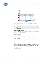
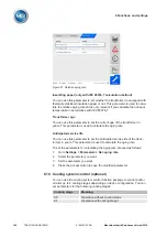
Figure 85: Schematic diagram of limit value monitoring (taking example of "Upper
limit value")
1
Limit value
4
Delay time
2
Hysteresis
A
Duration of set "behavior"
3
Measured value
Relative/absolute limit value
You can use this parameter to set whether the device is to use the "Absolute
limit value" or "Relative limit value".
Absolute limit value
You can use this parameter to set the limit value as a fixed absolute value.
Unlike the relative value, this limit is not dependent on a reference value.
Relative limit value
You can use this parameter to set the limit value relative to a reference val-
ue.
Hysteresis limit value
You can use this parameter to set the hysteresis. For "Upper limit value", the
hysteresis is deducted from the limit value and for "Lower limit value", it is
added to the limit value. When a limit value is violated, the set device behav-
ior is only reset once the measured value has exceeded the hysteresis. The
purpose of the hysteresis is to allow the device to ignore small fluctuations
around the limit value.
Содержание TRAFOGUARD ISM
Страница 1: ...Monitoring System TRAFOGUARD ISM Operating Instructions 5163667 00 EN ...
Страница 222: ......
Страница 223: ......

