


U S I N G M I C R O E X P R E S S C O N S O L E
39
Express “listens” to MMC transport commands
from any devices (or computer software)
connected to this icon.
For MMC transport control of the Micro Express
from the computer, enable the
transport master
option as shown Figure 6-18 on page 45. Doing so
makes the Micro Express follow MMC transport
commands sent from software.
Connecting a MMC controller to the Micro
Express
If you would like to control the Micro Express from
a MMC controller connected to one of the Micro
Express’s MIDI inputs, connect the device’s input
cable to the Transport In icon as demonstrated
below in Figure 6-11.
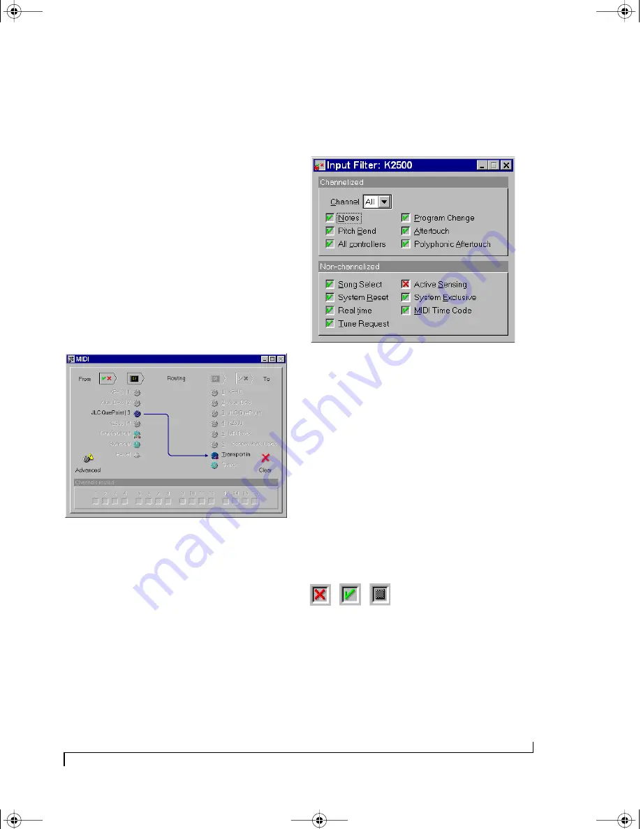
Figure 6-11: To control the Micro Express from a MMC controller such
as JLCooper’s CuePoint, connect the device to the Transport In icon as
shown here.
FILTER WINDOW
The Filter window is used to filter unwanted MIDI
data passing through the ports of the Micro
Express. Both inputs and outputs have filter
settings and each port’s settings is independent of
the others. A port’s Filter window is divided into
two sections. The upper section contains filter
settings for “channelized” MIDI messages (those
that are sent on a particular MIDI channel, such as
“note” or “Pitch Bend” messages) and the lower
part contains filter settings for “non-channelized”
MIDI messages (those that are not sent on a
particular channel, such as “System Exclusive”
messages).
Figure 6-12: The Filter window for the input named “K2500”.
Changing a filter setting
To filter MIDI messages for a particular port:
1
Click on the port’s icon in the MIDI Routing
window.
2
With the port selected, click on the “filter”
button above the selected port (or just double-click
the icon).
3
Now, with the port’s Filter window open, adjust
the message check boxes so the Micro Express
performs your desired message filtering as
explained below in Figure 6-13.
Figure 6-13: A red “X” means data will be filtered. A green check mark
means the data will not be filtered. A “hatched out” box indicates that
data is both filtered on one or more channels and not filtered on one
or more channels. The non-channelized filters will never show the
hatched-out box, since they apply to all channels.
!USB Interfaces Manual Book Page 39 Tuesday, October 10, 2000 12:43 PM
Содержание micro express-USB
Страница 1: ...C M Y CM MY CY CMY K...
Страница 6: ...IV USB Interfaces Manual Book Page iv Tuesday October 10 2000 12 43 PM...
Страница 7: ...All Users PartI ForAllUsers USB Interfaces Manual Book Page 5 Tuesday October 10 2000 12 43 PM...
Страница 8: ...All Users USB Interfaces Manual Book Page 6 Tuesday October 10 2000 12 43 PM...
Страница 27: ...XT Micro Users PartII ForXT MicroUsers USB Interfaces Manual Book Page 25 Tuesday October 10 2000 12 43 PM...
Страница 28: ...XT Micro Users USB Interfaces Manual Book Page 26 Tuesday October 10 2000 12 43 PM...
Страница 83: ...MPT AV Users PartIII ForMTPAVUsers USB Interfaces Manual Book Page 81 Tuesday October 10 2000 12 43 PM...
Страница 84: ...MPT AV Users USB Interfaces Manual Book Page 82 Tuesday October 10 2000 12 43 PM...
Страница 132: ...S Y N C H R O N I Z A T I O N W I T H T H E A V 130 USB Interfaces Manual Book Page 130 Tuesday October 10 2000 12 43 PM...
Страница 141: ...Appendices PartIV Appendices USB Interfaces Manual Book Page 139 Tuesday October 10 2000 12 43 PM...
Страница 142: ...Appendices USB Interfaces Manual Book Page 140 Tuesday October 10 2000 12 43 PM...


