Accessories 2 - 19
Four Slot Battery Charger Installation
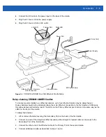
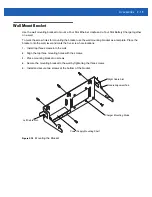
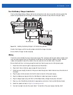
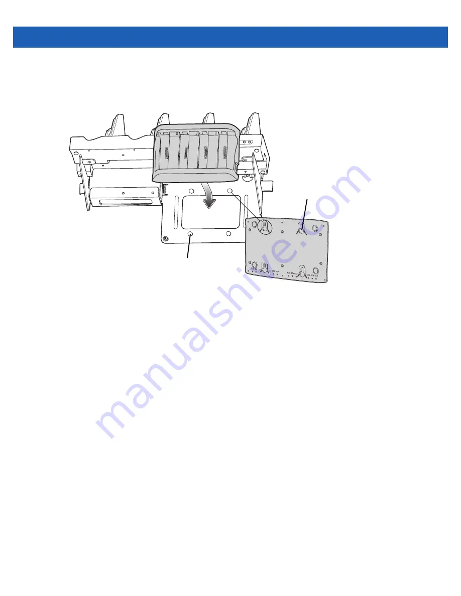
The Four Slot Spare Battery Charger has four mounting slots on the back. Around the slots are guides that
assist in proper alignment of the charger onto the mounting bracket. Gravity holds the charger in place.
Figure 2-18
Installing the Battery Charger onto the Mounting Bracket
Position the charger over the mounting studs and slide the charger into place.
Ensure that the charger is seated properly.
Wiring
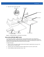
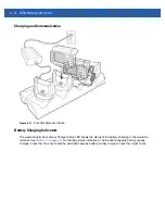
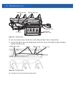
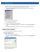
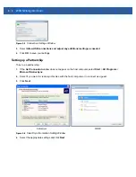
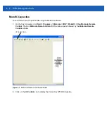
The AC line cord provides AC power to the power supply. The mounting bracket power cable provides power
from the power supply to the Four Slot Ethernet cradle and the Four Slot Spare Battery Charger. Ethernet
cables (not supplied) connects the cradle to the local network and to another cradle, if required.
Ensure that the AC line cord is long enough to reach from the AC power source to the power supply.
1.
Route the AC line cord through the right cable slot of the bracket.
2.
Plug the AC line cord into the power supply AC input connector.
3.
Route the power supply connector of the power cable through the cradle channel and out the left side of
the cradle.
4.
Plug the power cable connector into the DC output connector on the power supply.
5.
Plug the cradle power plug into the Four Slot Ethernet cradle input power connector.
6.
Plug the charger power plug onto the Four Slot Spare battery Charger input power connector.
7.
Plug one end of the Ethernet cable into the appropriate connector on the Four Slot Ethernet cradle.
8.
9.
Use two tie-wraps to secure the power cable Y connection to the power supply mounting shelf.
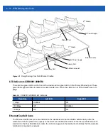
Mounting Studs
Mounting Slots
Содержание WT41N0
Страница 1: ...WT41N0 WEARABLE TERMINAL INTEGRATOR GUIDE ...
Страница 2: ......
Страница 3: ...WT41N0 INTERGRATOR GUIDE 72E 160600 01 Rev A December 2012 ...
Страница 6: ...iv WT41N0 Integrator Guide ...
Страница 18: ...xvi WT41N0 Integrator Guide ...
Страница 46: ...2 18 WT41N0 Integrator Guide Figure 2 17 Securing the Four Slot Ethernet Cradle to the Mounting Bracket ...
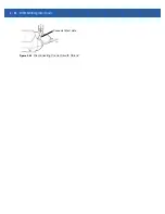
Страница 54: ...2 26 WT41N0 Integrator Guide Figure 2 28 Disconnecting Connector with Shroud Connector Eject Hole ...
Страница 60: ...3 6 WT41N0 Integrator Guide ...
Страница 64: ...4 4 WT41N0 Integrator Guide ...
Страница 118: ...7 16 WT41N0 Integrator Guide ...
Страница 122: ...8 4 WT41N0 Integrator Guide ...
Страница 154: ...A 20 WT41N0 Integrator Guide ...
Страница 156: ...B 2 WT41N0 User Guide ...
Страница 170: ...Index 4 WT41N0 Integrator Guide ...
Страница 171: ......

