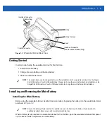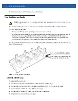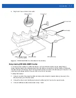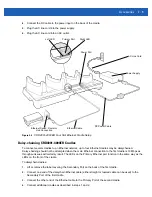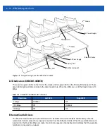
Getting Started
1 - 5
3.
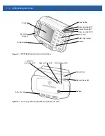
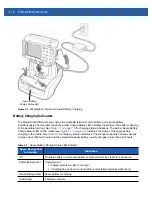
The wearable terminal starts to charge automatically. The amber Charge Status LED lights to indicate the
charge status. See
for charging indications.
Charging Spare Batteries
Use the following accessories to charge spare batteries:
•
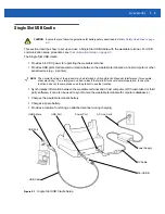
Single Slot USB cradle
•
Four Slot Spare Battery charger.
To charge a spare battery:
1.
Ensure the accessory used to charge the spare battery is connected to the appropriate power source.
2.
Insert the spare battery into the accessory’s spare battery charging slot with the charging contacts facing
down (over the charging pins) and gently press down on the battery to ensure proper contact.
3.
The battery starts to charge automatically. The amber charge LED on the accessory lights to show the
charge status. See
for accessory charge LED indicator definitions.
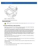
Removing the Main Battery
To remove the main battery:
1.
Prior to removing the battery, ensure that the wearable terminal is in suspend mode. If the wearable
terminal is not in suspend mode, press the Power button to place the wearable terminal in suspend mode.
2.
Press the battery release button. The battery partially ejects from the wearable terminal.
3.
Remove the battery from the wearable terminal.
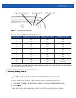
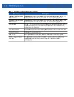
Table 1-1
Wearable Terminal LED Charge Indicators
LED
Indication
Off
Wearable terminal is not in cradle. Wearable terminal not placed correctly. Charger is
not powered.
Fast Blinking Amber
Charging error:
•
Temperature is too low or too high.
•
Charging has gone on too long without completing (typically eight hours).
Slow Blinking Amber
Wearable terminal is charging.
Solid Amber
Charging complete.
Note: When the battery is initially inserted in the wearable terminal, the amber LED
flashes once if the battery power is low or the battery is not fully inserted.
Содержание WT41N0
Страница 1: ...WT41N0 WEARABLE TERMINAL INTEGRATOR GUIDE ...
Страница 2: ......
Страница 3: ...WT41N0 INTERGRATOR GUIDE 72E 160600 01 Rev A December 2012 ...
Страница 6: ...iv WT41N0 Integrator Guide ...
Страница 18: ...xvi WT41N0 Integrator Guide ...
Страница 46: ...2 18 WT41N0 Integrator Guide Figure 2 17 Securing the Four Slot Ethernet Cradle to the Mounting Bracket ...
Страница 54: ...2 26 WT41N0 Integrator Guide Figure 2 28 Disconnecting Connector with Shroud Connector Eject Hole ...
Страница 60: ...3 6 WT41N0 Integrator Guide ...
Страница 64: ...4 4 WT41N0 Integrator Guide ...
Страница 118: ...7 16 WT41N0 Integrator Guide ...
Страница 122: ...8 4 WT41N0 Integrator Guide ...
Страница 154: ...A 20 WT41N0 Integrator Guide ...
Страница 156: ...B 2 WT41N0 User Guide ...
Страница 170: ...Index 4 WT41N0 Integrator Guide ...
Страница 171: ......


