MVME162 Functional Description
MVME162/D2
4-3
4
C
aution
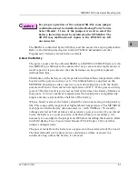
For proper operation of the onboard SRAM, some jumper
combination must be installed on the Backup Power Source
Select Header. If one of the jumpers is used to select the
battery, the battery must be installed on the MVME162. The
SRAM may malfunction if inputs to the DS1210S are left
unconnected.
The SRAM is controlled by the MCchip, and the access time is programmable.
Refer to the MCchip description in the MVME162 Embedded Controller
Programmer’s Reference Guide for more detail.
About the Battery
The power source for the onboard SRAM is a RAYOVAC FB1225 battery with
two BR1225 type lithium cells, socketed for easy removal and replacement. A
small capacitor is provided so that the batteries can be quickly replaced
without data loss.
The lifetime of the battery is very dependent on the ambient temperature of the
board and the power-on duty cycle. The lithium battery supplied on the
MVME162 should provide at least two years of backup time with the board
powered off and with an ambient temperature of 40° C. If the power-on duty
cycle is 50% (the board is powered on half of the time), the battery lifetime is
four years. At lower ambient temperatures the backup time is significantly
longer and may approach the shelf life of the battery.
When a board is stored, the battery should be disconnected to prolong battery
life. This is especially important at high ambient temperatures. The MVME162
is shipped with the battery disconnected (i.e., with 5V standby
voltage selected as both primary and secondary power source). If you intend
to use the battery as a power source, whether primary or secondary, it is
necessary to reconfigure the jumpers on J20 before installing the module. Refer
to SRAM Backup Power Source Select Header J20 in Chapter 2 for available
jumper configurations.
The power leads from the battery are exposed on the solder side of the board.
The board should not be placed on a conductive surface or stored in a
conductive bag unless the battery is removed.
Содержание MVME162
Страница 1: ...MVME162 Embedded Controller User s Manual MVME162 D2 ...
Страница 6: ......
Страница 10: ...x ...
Страница 12: ...xii ...
Страница 14: ...xiv ...
Страница 52: ...Hardware Preparation and Installation 2 26 MVME162 Embedded Controller User s Manual 2 ...
Страница 64: ...Operating Instructions 3 12 User s Manual 3 This page intentionally left blank ...
Страница 78: ...Operating Instructions 3 26 User s Manual 3 ...
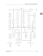
Страница 92: ...Functional Description 4 14 User s Manual 4 Figure 4 1 MVME162 Main Module Block Diagram ...
Страница 94: ...Functional Description 4 16 User s Manual 4 Figure 4 2 Parity DRAM Mezzanine Module Block Diagram ...
Страница 106: ...Index IN 4 User s Manual I N D E X ...

