Functional Description
4-10
User’s Manual
4
Programmable Tick Timers
Four 32-bit programmable tick timers with 1
µ
s
resolution are provided in the
MCchip and two 32-bit programmable tick timers are provided in the optional
VMEchip2. The tick timers can be programmed to generate periodic
interrupts to the processor. Refer to the MCchip and VMEchip2 descriptions
in the MVME162 Embedded Controller Programmer’s Reference Guide for detailed
programming information.
Watchdog Timer
A watchdog timer is provided in both the MCchip and the optional VMEchip2.
The timers operate independently but in parallel. When the watchdog timers
are enabled, they must be reset by software within the programmed time or
they will time out. The watchdog timers can be programmed to generate a
SYSRESET signal, local reset signal, or board fail signal if they time out. Refer
to the VMEchip2 and MCchip descriptions in the MVME162 Embedded
Controller Programmer’s Reference Guide for detailed programming information.
Software-Programmable Hardware Interrupts
Eight software-programmable hardware interrupts are provided by the
VMEchip2. These interrupts allow software to create a hardware interrupt.
Refer to the VMEchip2 desciption in the MVME162 Embedded Controller
Programmer’s Reference Guide for detailed programming information.
Local Bus Timeout
The MVME162 provides timeout functions in the VMEchip2 and the MCchip
for the local bus. When the timer is enabled and a local bus access times out,
a Transfer Error Acknowledge (TEA) signal is sent to the local bus master. The
timeout value is selectable by software for 8
µ
sec, 64
µ
sec, 256
µ
sec, or infinity.
The local bus timer does not operate during VMEbus bound cycles. VMEbus
bound cycles are timed by the VMEbus access timer and the VMEbus global
timer. Refer to the VMEchip2 and MCchip descriptions in the MVME162
Embedded Controller Programmer’s Reference Guide for detailed programming
information.
The MCchip also provides local bus timeout logic for MVME162s without the
optional VMEbus interface (i.e., without the VMEchip2).
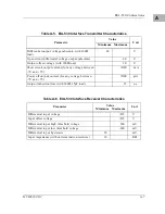
Timing Performance
This section provides performance information for the MVME162. The
MVME162 is designed to operate at 25 MHz.
Содержание MVME162
Страница 1: ...MVME162 Embedded Controller User s Manual MVME162 D2 ...
Страница 6: ......
Страница 10: ...x ...
Страница 12: ...xii ...
Страница 14: ...xiv ...
Страница 52: ...Hardware Preparation and Installation 2 26 MVME162 Embedded Controller User s Manual 2 ...
Страница 64: ...Operating Instructions 3 12 User s Manual 3 This page intentionally left blank ...
Страница 78: ...Operating Instructions 3 26 User s Manual 3 ...
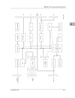
Страница 92: ...Functional Description 4 14 User s Manual 4 Figure 4 1 MVME162 Main Module Block Diagram ...
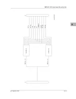
Страница 94: ...Functional Description 4 16 User s Manual 4 Figure 4 2 Parity DRAM Mezzanine Module Block Diagram ...
Страница 106: ...Index IN 4 User s Manual I N D E X ...

