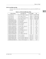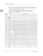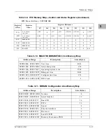
Operating Instructions
3-4
User’s Manual
3
N
otes
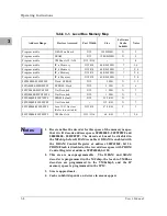
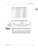
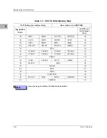
1. Reset enables the decoder for this space of the memory map so
that it will decode address spaces $FF800000 - $FF9FFFFF and
$00000000 - $003FFFFF. The decode at 0 must be disabled in
the MCchip before DRAM is enabled. DRAM is enabled with
the DRAM Control Register at address $FFF42048, bit 24.
PROM/Flash is disabled at the low address space with PROM
Control Register at address $FFF42040, bit 20.
2. This area is user-programmable. The DRAM and SRAM
decoder is programmed in the MCchip, the local-to-VMEbus
decoders are programmed in the VMEchip2, and the IP
memory space is programmed in the IPIC.
3. Size is approximate.
4. Cache inhibit depends on devices in area mapped.
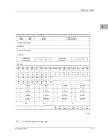
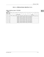
Table 3-1. Local Bus Memory Map
Address Range
Devices Accessed
Port Width
Size
Software
Cache
Inhibit
Notes
Programmable
DRAM on Board
D32
1MB-8MB
N
2
Programmable
SRAM
D32
128KB-2MB
N
2
Programmable
VMEbus A32/A24
D32/D16
--
?
4
Programmable
IP_a Memory
D32-D8
64 KB-8 MB
?
2, 4
Programmable
IP_b Memory
D32-D8
64 KB-8 MB
?
2, 4
Programmable
IP_c Memory
D32-D8
64 KB-8 MB
?
2, 4
Programmable
IP_d Memory
D32-D8
64 KB-8 MB
?
2, 4
$FF800000-$FF9FFFFF
Flash/EPROM
D32
2 MB
N
1, 5
$FFA00000-$FFBFFFFF
EPROM/Flash
D32
2 MB
N
6
$FFC00000-$FFCFFFFF
Not Decoded
D32
1 MB
N
7
$FFD00000-$FFDFFFFF
Not Decoded
D32
1 MB
N
7
$FFE00000-$FFE7FFFF
SRAM default
D32
512 KB
N
--
$FFE80000-$FFEFFFFF
Not Decoded
--
512 KB
N
7
$FFF00000-$FFFEFFFF
Local I/O Devices
(Refer to next table)
D32-D8
878 KB
Y
3
$FFFF0000-$FFFFFFFF
VMEbus A16
D32/D16
64 KB
?
2, 4
Содержание MVME162
Страница 1: ...MVME162 Embedded Controller User s Manual MVME162 D2 ...
Страница 6: ......
Страница 10: ...x ...
Страница 12: ...xii ...
Страница 14: ...xiv ...
Страница 52: ...Hardware Preparation and Installation 2 26 MVME162 Embedded Controller User s Manual 2 ...
Страница 64: ...Operating Instructions 3 12 User s Manual 3 This page intentionally left blank ...
Страница 78: ...Operating Instructions 3 26 User s Manual 3 ...
Страница 92: ...Functional Description 4 14 User s Manual 4 Figure 4 1 MVME162 Main Module Block Diagram ...
Страница 94: ...Functional Description 4 16 User s Manual 4 Figure 4 2 Parity DRAM Mezzanine Module Block Diagram ...
Страница 106: ...Index IN 4 User s Manual I N D E X ...

