EIA-530 Connections
MVME162/D2
A-5
A
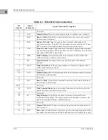
4
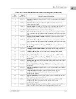
RTS_A
Request to Send (A).
Output from DTE to DCE when required to transmit
a message.
5
CTS_A
Clear to Send (A).
Input to DTE from DCE to indicate that message
transmission can begin.
6
DSR_A
Data Set Ready (A).
Input to DTE from DCE to indicate that the DCE is
ready to send or receive data. In DCE configuration, always true.
7
SIG GND
Signal Ground.
Common return line for all signals.
8
DCD_A
Data Carrier Detect
(A). Receive line signal detector output from DCE to
DTE to indicate that valid data is being transferred to the DTE on the RxD
line.
9
RxC_B
Receive Signal Element Timing—DCE (B).
Control signal that clocks
input data.
10
DCD_B
Data Carrier Detect
(B). Receive line signal detector output from DCE to
DTE to indicate that valid data is being transferred to the DTE on the RxD
line.
11
TxCO_B
Transmit Signal Element Timing—DTE (B).
Control signal that clocks
output data.
12
TxC_B
Transmit Signal Element Timing—DCE (B).
Control signal that clocks
input data.
13
CTS_B
Clear to Send (B).
Input to DTE from DCE to indicate that message
transmission can begin.
14
TxD_B
Transmit Data (B).
Data to be transmitted; output from DTE to DCE.
15
TxC_A
Transmit Signal Element Timing—DCE (A).
Control signal that clocks
input data.
16
RxD_B
Receive Data (B).
Data which is demodulated from the receive line; input
from DCE to DTE.
17
RxC_A
Receive Signal Element Timing—DCE (A).
Control signal that clocks
input data.
18
RTS_B
Request to Send (B).
Output from DTE to DCE when required to transmit
a message.
19
LL_A
Local Loopback (A).
Reroutes signal within local DCE. In DTE
configuration, always tied inactive and driven false. In DCE
configuration, ignored
20
DTR_A
Data Terminal Ready (A).
Output from DTE to DCE indicating that the
DTE is ready to send or receive data.
21
RL_A
Remote Loopback (A).
Reroutes signal within remote DCE. In DTE
configuration, always tied inactive and driven false. In DCE
configuration, ignored.
22
DSR_B
Data Set Ready (B).
Input to DTE from DCE to indicate that the DCE is
ready to send or receive data. In DCE configuration, always true.
Table A-4. Serial Port B EIA-530 Interconnect Signals (Continued)
Pin
Number
Signal
Mnemonic
Signal Name and Description
Содержание MVME162
Страница 1: ...MVME162 Embedded Controller User s Manual MVME162 D2 ...
Страница 6: ......
Страница 10: ...x ...
Страница 12: ...xii ...
Страница 14: ...xiv ...
Страница 52: ...Hardware Preparation and Installation 2 26 MVME162 Embedded Controller User s Manual 2 ...
Страница 64: ...Operating Instructions 3 12 User s Manual 3 This page intentionally left blank ...
Страница 78: ...Operating Instructions 3 26 User s Manual 3 ...
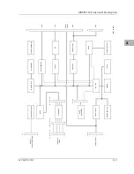
Страница 92: ...Functional Description 4 14 User s Manual 4 Figure 4 1 MVME162 Main Module Block Diagram ...
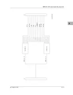
Страница 94: ...Functional Description 4 16 User s Manual 4 Figure 4 2 Parity DRAM Mezzanine Module Block Diagram ...
Страница 106: ...Index IN 4 User s Manual I N D E X ...

