General Description
MVME162/D2
1-7
1
VMEbus Interface
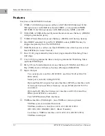
The optional VMEchip2 ASIC is the VMEbus interface for the MVME162.
(This option is a factory build and cannot be added in the field.) VMEchip2
features include:
❏
Two programmable 32-bit tick timers
❏
A programmable watchdog timer
❏
Programmable map decoders for the master and slave interfaces
❏
A VMEbus to/from local bus DMA controller
❏
A VMEbus to/from local bus non-DMA programmed access interface
❏
A VMEbus interrupter
❏
A VMEbus system controller
❏
A VMEbus interrupt handler
❏
A VMEbus requester
Processor-to-VMEbus transfers can be D8, D16, or D32. VMEchip2 DMA
transfers to the VMEbus, however, can be D16, D32, D16/BLT, D32/BLT, or
D64/MBLT.
No-VMEbus-Interface Option
If desired, the MVME162 can function as an embedded controller without a
VMEbus interface (i.e., without the optional VMEchip2). Contact your local
Motorola sales office for ordering information.
MCchip
The Memory Controller (MCchip) ASIC provides four 32-bit programmable
tick timers and an interface to the LAN chip, SCSI chip, serial port chip,
BBRAM, PROM/Flash, SRAM, DRAM, reset control, watchdog timers, access
timers, and interrupter logic.
Flash Memory and EPROM
The MVME162 is equipped with 1MB of Flash memory and an EPROM socket
ready for the installation of the EPROM, which may be ordered separately.
Flash memory is either a single device organized in a 1Mbit x 8 configuration
or four devices organized in a 256Kbit x 8 configuration. The EPROM location
is a standard JEDEC 32-pin PLCC capable of four Mbit densities (128 Kbit x 8;
Содержание MVME162
Страница 1: ...MVME162 Embedded Controller User s Manual MVME162 D2 ...
Страница 6: ......
Страница 10: ...x ...
Страница 12: ...xii ...
Страница 14: ...xiv ...
Страница 52: ...Hardware Preparation and Installation 2 26 MVME162 Embedded Controller User s Manual 2 ...
Страница 64: ...Operating Instructions 3 12 User s Manual 3 This page intentionally left blank ...
Страница 78: ...Operating Instructions 3 26 User s Manual 3 ...
Страница 92: ...Functional Description 4 14 User s Manual 4 Figure 4 1 MVME162 Main Module Block Diagram ...
Страница 94: ...Functional Description 4 16 User s Manual 4 Figure 4 2 Parity DRAM Mezzanine Module Block Diagram ...
Страница 106: ...Index IN 4 User s Manual I N D E X ...

