MVME162LX/D1
IN-3
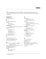
I
N
D
E
X
S
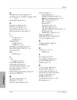
SCSI
FIFO buffer 4-11
interface 1-2, 1-8, 4-9
termination 4-9
terminator power 2-13
serial communications interface 4-5
serial interface modules (SIMs) 2-2
part numbers 2-4
port B configuration 4-6
selection 2-2
serial interface parameters A-3
serial interface signals A-1
serial ports 1-2, 1-6, 1-9, 2-2, A-1
SIM selection 2-2
software 1-9
specifications 1-3
SRAM
backup 4-2
backup power selection 2-7
support information 1-11
synchronous
clock selection 2-6, 4-6
communications 2-6, 4-6
system controller 2-10
system controller selection (J1) 2-5
system reset (SRST) 3-1, 3-25
T
tick timers 4-9
Time of Day clock 1-2
timeout functions 4-10
timers 1-2
TOD clock memory map 3-20
transition modules 1-6, 1-9, 2-13, 4-6
installation 2-10
serial I/O connectors 4-6
transmitters, EIA-232-D A-3
transmitters, EIA-530 A-7
U
user-definable jumpers 2-8
V
VMEbus
address/data configurations 2-12
interface 1-2, 1-7, 4-5
system controller functions 4-5
VMEchip2 1-7
W
watchdog timers 4-10
Содержание MVME162
Страница 1: ...MVME162 Embedded Controller User s Manual MVME162 D2 ...
Страница 6: ......
Страница 10: ...x ...
Страница 12: ...xii ...
Страница 14: ...xiv ...
Страница 52: ...Hardware Preparation and Installation 2 26 MVME162 Embedded Controller User s Manual 2 ...
Страница 64: ...Operating Instructions 3 12 User s Manual 3 This page intentionally left blank ...
Страница 78: ...Operating Instructions 3 26 User s Manual 3 ...
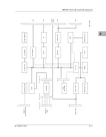
Страница 92: ...Functional Description 4 14 User s Manual 4 Figure 4 1 MVME162 Main Module Block Diagram ...
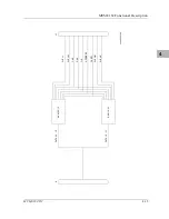
Страница 94: ...Functional Description 4 16 User s Manual 4 Figure 4 2 Parity DRAM Mezzanine Module Block Diagram ...
Страница 106: ...Index IN 4 User s Manual I N D E X ...

