Operating Instructions
3-24
User’s Manual
3
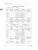
Interrupt Acknowledge Map
The local bus distinguishes interrupt acknowledge cycles from other cycles by
placing the binary value %11 on TT1-TT0. It also specifies the level that is
being acknowledged using TM2-TM0. The interrupt handler selects which
device within that level is being acknowledged.
VMEbus Memory Map
This section describes the mapping of local resources as viewed by VMEbus
masters.
VMEbus Accesses to the Local Bus
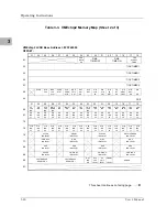
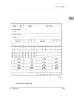
The VMEchip2 includes a user-programmable map decoder for the VMEbus-
to-local-bus interface. The map decoder allows you to program the starting
and ending address and the modifiers the MVME162 responds to.
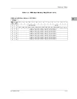
VMEbus Short I/O Memory Map
The VMEchip2 includes a user-programmable map decoder for the GCSR.
The GCSR map decoder allows you to program the starting address of the
GCSR in the VMEbus short I/O space.
Software Initialization
Most functions that have been done with switches or jumpers on other
modules are done by setting control registers on the MVME162. At powerup
or reset, the EPROMs that contain the 162Bug debugging package set up the
default values of many of these registers.
Specific programming details may be determined by study of the M68040
Microprocessor User’s Manual. Then check the details of all the MVME162
onboard registers as given in the MVME162 Embedded Controller Programmer’s
Reference Guide.
Multi-MPU Programming Considerations
Good programming practice dictates that only one MPU at a time have control
of the MVME162 control registers. Of particular note are:
❏
Registers that modify the address map
❏
Registers that require two cycles to access
❏
VMEbus interrupt request registers
Содержание MVME162
Страница 1: ...MVME162 Embedded Controller User s Manual MVME162 D2 ...
Страница 6: ......
Страница 10: ...x ...
Страница 12: ...xii ...
Страница 14: ...xiv ...
Страница 52: ...Hardware Preparation and Installation 2 26 MVME162 Embedded Controller User s Manual 2 ...
Страница 64: ...Operating Instructions 3 12 User s Manual 3 This page intentionally left blank ...
Страница 78: ...Operating Instructions 3 26 User s Manual 3 ...
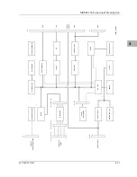
Страница 92: ...Functional Description 4 14 User s Manual 4 Figure 4 1 MVME162 Main Module Block Diagram ...
Страница 94: ...Functional Description 4 16 User s Manual 4 Figure 4 2 Parity DRAM Mezzanine Module Block Diagram ...
Страница 106: ...Index IN 4 User s Manual I N D E X ...

