


9-55
Magnetek Quattro AC Quick Reference
iControl AC
9
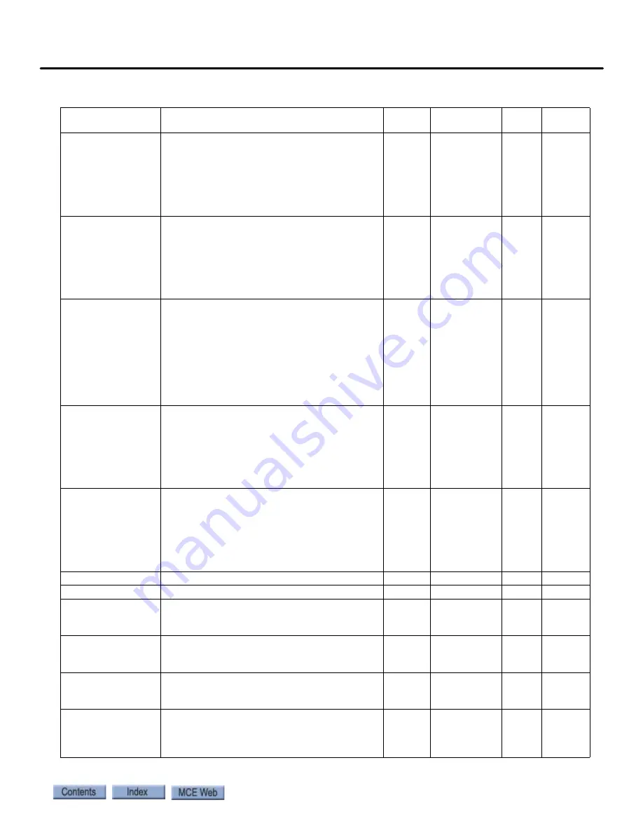
SER2 FLT TOL
Maximum time to allow between reception of
packets in serial mode
Sec
0 – 2.00
0.04
0.04
ARB INERTIA
Anti rollback inertia. Inertia/gain setting when
drive is in ARB Mode. Too high a setting may
cause motor instability. If motor growls or
vibrates, lower setting. Too low a setting may
cause excessive rollback. Recommend: Start
value at same value as system inertia (INER-
TIA).
None
0.10 – 20.00 0.30
0.30
ARB START TIME
Anti rollback start time. Dwell time between
logic output SPD REG RLS and brake starting
to pick. ARB will not become activated until
ARL START TIME has occurred. Too long a
value will cause major rollback. Too short a
value will cause ARB to begin while brake is
still set. Adjust to begin just as brake is lifting.
Sec
0.00 – 5.00
2.00
*
ARB DECAY RATE
Anti rollback decay rate. Determines slew rate
for torque while in ARB Mode. The higher the
value, the more torque change may occur. The
lower the value, the less torque change may
occur. Setting to maximum 0.99 indicates lim-
ited decay. The faster the brake lifts, the
higher this value should be. Adjusting this
may cause ARB RESPONSE to also need
adjustment.
Sec
0.500 – 0.999 0.850
*
ARB RESPONSE
Anti rollback response. Determines how
quickly drive will react to brake opening. For
most systems, should be close to 20. Too high
a value may cause large torque bumps, more
rollback. The lower the value of ARB DECAY
RATE, the lower the value of ARB RESPONSE
will need to be to hold car from rollback.
None
5 – 100
25
*
ARB TORQUE TIME Anti rollback torque time. Helps smooth out
torque requirement from drive to motor. Set
at zero, drive will step up torque as required
to hold motor. The higher the value, the
smoother the torque transition to the motor.
However, with higher values more rollback
may occur.
Sec
0.00 – 10.00 0.00
*
NOTCH FILTER FRQ Determines notch filter center frequency
Hz
5 – 60
20
20
NOTCH FILT DEPTH Determines notch filter maximum attenuation %
0 – 100
0
0
MSPD DELAY 1-4
Multi step speed delay 1 – 4. Determines rec-
ognition time delay for a defined multi-step
speed command.
Sec
0.000 –
10.000
0.000
0.000
MID SPEED LEVEL
Sets level/threshold for mid speed detection.
Used only to generate mid speed logic output.
Units in percent of contract speed.
%
0.00 – 110.00 80.00
80.00
BRK FAULT LEVEL
Sets level of speed error that will cause drive
to fault with a BRK IS OPEN fault during an
auto align or auto tune.
%
0.0 – 20.0
2.0
2.0
ENCDR FLT SENSE
Determines percentage of voltage rise to
occur before an Encoder Fault occurs due to
voltage rise at beginning of run. Units in per-
cent of Rated Mtr Volts.
%
10 – 100
30
30
Table 10. Quattro PM Elevator Drive, iControl
Содержание Nidec iControl
Страница 1: ...MOTION CONTROL ENGINEERING User Guide iControl with AC Drive...
Страница 15: ......
Страница 23: ...1 8 Manual 42 02 2223 iControl Overview...
Страница 75: ...2 52 Manual 42 02 2223 Construction Mode...
Страница 89: ...3 14 Manual 42 02 2223 Inspection Mode...
Страница 138: ...4 49 Safety Tests iControl AC 4 Figure 4 6 Typical Brake Test Circuit Machine Brake Emergency Brake...
Страница 280: ...6 95 iControl Circuit Board Quick References iControl AC 6 Figure 6 7 Earthquake Board Supporting Information...
Страница 303: ...6 118 Manual 42 02 2223 Troubleshooting...