


9-52 Manual # 42-02-2223
Reference
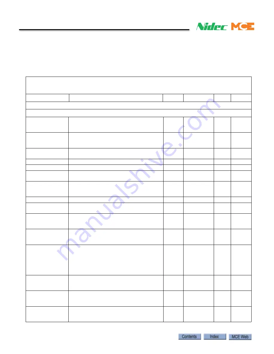
Magnetek Quattro AC Quick Reference
This section includes quick reference information for the Magnetek Quattro AC Elevator drive
parameters. Please refer to the Magnetek drive manual provided with iControl for a detailed
explanation. Enter the settings you make while adjusting into the Field Setting column.
Table 10. Quattro PM Elevator Drive, iControl
WARNING: Do not change drive parameters while elevator is running. Incorrect drive parameters
can cause erratic operation. Parameters with an asterisk must be set correctly for specific motor/
machine / job. Refer to drive manual for detailed information.
Parameter
Description
Units
Range
Def
Fac
Adjust A0
A1 Drive sub menu
CONTRACT CAR SPD Elevator Contract Speed
fpm
0.0 – 1500.0 100.0 *
CONTRACT MTR SPD Motor Speed at elevator contract speed
RPM
30.0 – 3000.0 50.0
*
RESPONSE
Sets sensitivity of drive speed regulator in
terms of speed regulator bandwidth in radians
rad/sec 1.0 – 20.0
10.0
10.0
INERTIA
Inertia /torque ratio as seen by the drive
sec
0.25 – 50.00 2.00
2.00
INNER LOOP XOVER This parameter is used as a stiffness factor
rad/sec 0.1 – 20.0
2.0
2.0
GAIN REDUCE MULT Percentage of “response” the speed regulator
should use in “low gain” mode
%
10 – 100
100
100
GAIN CHNG LEVEL When the HI/LO GAIN SRC in submenu C1 is
set to internal, the drive will control the high/
low gain switch
% of
rated spd
0.0 – 100.0
100.0 100.0
TACH RATE GAIN
Reduces effects of rope resonance or stretch none
0.0 – 30.0
0.0
0.0
SPD PHASE MARGIN Sets phase margin of speed regulator assum-
ing a pure inertial load
degrees 45 – 90
80
80
RAMPED STOP TIME Used only by torque ramp down function dur-
ing a stop sets time to decrease motor rated
torque to zero.
sec
0.00 – 2.50
0.20
0.20
CONTACT FLT TIME Determines allowable time for motor contac-
tor feedback to be out of sync with com-
manded state before contactor FLT occurs.
sec
0.10 – 5.00
0.50
0.50
BRAKE PICK TIME
If brake pick CNFM is set to internal time, this
parameter sets time the drive waits before it
assumes brake has been picked. If brake pick
CNFM is set to external TB, parameter sets
time drive waits receive a brake pick confir-
mation before a brake pick fault is declared
sec
0.00 – 5.00
1.00
0.0
BRAKE HOLD TIME Determines time drive will wait until a BRK
HOLD FLT is declared if a logic input is set to
MECH BRK HOLD
sec
0.00 – 5.00
0.50
0.10
OVERSPEED LEVEL Sets percentage of rated speed drive uses (in
conjunction with OVERSPEED TIME) to deter-
mine when an OVERSPEED fault occurs.
% of
contract
spd
90.0 – 150.0 115.0 115.0
OVERSPEED TIME
Sets time drive can be at or above OVER-
SPEED LEVEL (A1), before it declares OVER-
SPEED FLT.
sec
0.00 – 9.99
1.00
1.00
Содержание Nidec iControl
Страница 1: ...MOTION CONTROL ENGINEERING User Guide iControl with AC Drive...
Страница 15: ......
Страница 23: ...1 8 Manual 42 02 2223 iControl Overview...
Страница 75: ...2 52 Manual 42 02 2223 Construction Mode...
Страница 89: ...3 14 Manual 42 02 2223 Inspection Mode...
Страница 138: ...4 49 Safety Tests iControl AC 4 Figure 4 6 Typical Brake Test Circuit Machine Brake Emergency Brake...
Страница 280: ...6 95 iControl Circuit Board Quick References iControl AC 6 Figure 6 7 Earthquake Board Supporting Information...
Страница 303: ...6 118 Manual 42 02 2223 Troubleshooting...