


ൡಽͽ
MACHINE OPERATION
44
7
า
7
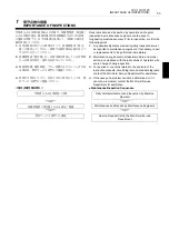
CAUTION
1.
Ғҭࡾщɥʹ˂ɹȾᣋȸȤɞȻȠǾ
Z
ᢉɥሉӦȨȮȲऻȾ
X
ᢉɥ͎ȪȹȢȳȨȗǿҒҭࡾщɥʹ˂ɹȞɜᤕȩȤɞ
ȻȠɂǾ
X
ᢉɥ॑ઃիȻࢱຒȪȽȗͱᏚɑȺሉӦȨȮȲऻ
Ⱦ
Z
ᢉɥሉӦȨȮȹȢȳȨȗǿ
ᵘҏ࿎իȻ॑ઃիɁࢱຒᵚ
1.
For center-work machining, move the Z-axis first and
then the X-axis to position the cutting tool at the
approach point. In the cutting tool retraction operation,
first retract the X-axis to a point where continued
cutting tool movement does not interfere with the
tailstock, and then move the Z-axis to the required
retraction position.
[Turret and tailstock interference]
2.
˿ᢉȟوᢆȪȹȗȽȗȻȠȾǾɹ˂ʳʽʒɥվҋȨȮȽȗ
ȺȢȳȨȗᴥʩ˂ʴʽɺӏࡾ˹ɥȢᴦǿɑȲǾ˿ᢉوᢆ
˹ȾȝȗȹɕǾ˿ᢉʣɬʴʽɺȾɹ˂ʳʽʒȟоɜȽȗ
ɛșȾȪȹȢȳȨȗǿ
ᵘᆍૺᵚ
2.
Do not discharge coolant when the spindle is not
rotating (except during milling operation). Take
measures to ensure that coolant does not enter the
spindle bearings when it is discharged while the
spindle is rotating.
[Spindle damage]
3.
G10
ɑȲɂʁʃʐʪ۰ୣɥ͎Ȫȹ
‘
ʹ˂ɹɴʟʅʍʒ
’
႕ᬂɁ
‘
цᣮ
’
ȾୣϏɥоӌȬɞȻǾ
G54
ᵻ
G59
ȬɌȹɁ
࣋ൈጕȺӏࡾՁཟȟպˢտȾʁʟʒȨɟɞɁȺาȪȹ
ȢȳȨȗǿ
ᵘࡾщɗҏ࿎իȟʋʭʍɹȽȼȻࢱຒǾൡಽɁᆍૺᵚ
3.
Note that if data is set for ‘COMMON’ on the ‘WORK
OFFSET’ screen by specifying G10 or system variable
commands, the workpiece zero point is shifted in the
same direction in all of the work coordinate systems,
G54 to G59.
[Tool/Turret and chuck interference, machine damage]
7-2
ɮʽʉʷʍɹ
Interlock
8
ឬ֖
8
WARNING
1.
ൡಽɥΈႊȬɞȻȠɂǾյሗɮʽʉʷʍɹൡᑤɥ
“
ӛ
”
ȾȪȹȢȳȨȗǿɗɓɥीȭ
“
ᜓ
”
ȾȪȹൡಽɥΈႊȬ
ɞȻȠɂǾͽȾ۹ȢɁԲ᪙ȟސ٣ȬɞȦȻɥᝓឧȪǾԚ
ґาȪȹȢȳȨȗǿ
“
ᜓ
”
ৰȺɁͽɥጶ̘ȪȲऻ
ɂǾյɮʽʉʷʍɹൡᑤɥ
“
ӛ
”
ȾȪȹȢȳȨȗǿ
ᵘ̷ᡵ̜Ǿᆍૺᵚ
1.
All interlock functions must be ON when operating the
machine. If necessary to operate the machine with
interlocks released, awareness of the dangers involved
and particular attention given to safety during machine
operation is essential. Following completion of the
operation, ensure interlocks are turned back ON
immediately.
[Serious injury/Machine damage]
2.
ʓɬɮʽʉʷʍɹൡᑤɁᣲɗ۶ȪȽȼɂȪȽȗȺȢȳ
Ȩȗǿ
2.
Do not modify or remove the door interlock function.
3.
ɮʽʉʷʍɹൡᑤɥᤈαȬɞȦȻȽȢǾࢠȾާпɥ॑ȟȤ
ȹൡಽɥΈႊȪȹȢȳȨȗǿ
3.
Do not put too much confidence in interlock function.
Ensure safety procedures are followed at all times.
7-3
ʑ˂ʉ
Data
7
า
7
CAUTION
1.
ᄊ᧸ȨɟȲʡʷɺʳʪǾൡಽҋᔸȾᜫްȨɟȹȗɞʛʳ
ʫ˂ʉȝɛɆоӌȨɟȲɴʟʅʍʒʑ˂ʉɂǾʚʍɹɬʍ
ʡɥɝίސȪȹȢȳȨȗǿ
ᵘʑ˂ʉɁᆍەǾૺ܅̜ᵚ
1.
Back up stored programs, parameters set before
shipping and offset data.
[Programs destroyed, parameter data and/or offset
data lost]
2
าᜤ
2
NOTE
ࣷᇋɂǾʚʍɹɬʍʡɥȶȹȗȽȗʑ˂ʉɁᆍૺȾߦȬɞૺ
ȾȷȗȹǾ͖ɥ២ȗɑȮɦǿ
Mori Seiki is not liable for problems resulting from destroyed
programs or lost data that have not been backed up.
2.
ʫʬʴɹʴɬɁͽɥᚐșȻȠɂǾࣷᇋɿ˂ʝʃᩌȾȧ
ᣵፅȢȳȨȗǿ
ᵘʑ˂ʉɁૺ܅ᵚ
2.
If necessary to perform a memory clear operation,
contact the Mori Seiki Service Department for
assistance.
[Data deleted]
Содержание NL1500/500
Страница 8: ......
Страница 9: ...CONTENTS FOR SAFE MACHINE OPERATION REGULAR MAINTENANCE TROUBLESHOOTING INDEX...
Страница 10: ......
Страница 19: ...FOR SAFE MACHINE OPERATION...
Страница 50: ......
Страница 51: ...1 1 CHAPTER 1 CHAPTER 1 REGULAR MAINTENANCE...
Страница 167: ...2 2 CHAPTER 2 CHAPTER 2 TROUBLESHOOTING...
Страница 181: ...181 ZERO POINT RETURN COMMAND ALARM TRIGGERED X X Axis Z Z Axis Y Y Axis...
Страница 232: ......
Страница 240: ......
Страница 242: ......