


- 7 -
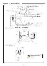
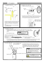
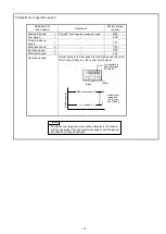
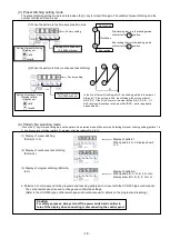
6. Installation of the position detector
(1) The installation of the position detector will differ according
to the sewing machine model, so please consult with your
sewing machine dealer for details.
The diagram on the left shows an example of the position
detector installation.
(2) Insert the connector from the position detector into the
control box position connector.
(3) To prevent malfunctions caused by static electricity, connect
the grounding wires (green/yellow) from the position
detector onto the sewing machine head.
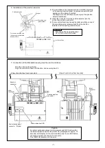
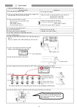
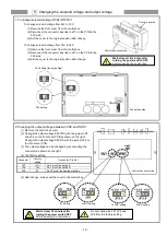
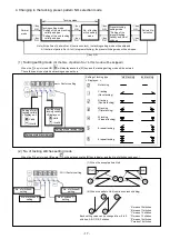
7. Connection of the Mitsubishi sewing machine and control box.
Wire the units as shown below.
Align the connector shape and direction, and securely insert it.
[View of control box from cover side]
[View of control box from box side]
This can not be used with except
XC-G, XC-F and XC-E Series.
Caution
Position detector
Stopper
This can be installed onto
the sewing machine table
as shown here.
Grounding wire
(green/yellow)
Control box
Lever
connector
Encoder
connector
Sewing machine
connector
Motor
connector
Control switch panel
connector (Option)
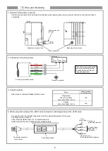
Status indication LED
Caution
For safety purposes, always turn the power switch OFF and wait for
the status indication LED or the [PWR. OF] (displayed for approx. 10
seconds) LED display on the control switch panel to turn OFF before
connecting or disconnecting each connector.
This [PWR.OF] display is not an error.


