


- 27 -
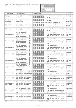
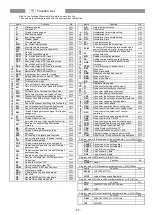
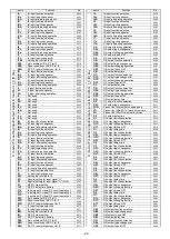
name
Function
No.
DN.
ON output delay time
0456
OO.
OO output function selection
0457
OOL.
OO output logic changeover
0458
OOT.
OO output forced OFF
0459
DO.
OO output delay time
0460
OP.
OP output function selection
0461
OPL.
OP output logic changeover
0462
OPT.
OP output forced OFF
0463
DP.
OP output delay time
0464
OQ.
OQ output function selection
0465
OQL.
OQ output logic changeover
0466
OQT.
OQ output forced OFF
0467
DQ.
OQ output delay time
0468
O.R.
OR output function selection
0469
O.RL.
OR output logic changeover
0470
O.RT.
OR output forced OFF
0471
DR.
OR output delay time
0472
PO.
Full wave output time for each output
0473
POD.
Output chopping duty except of FU output
0474
OTT.
Forced OFF timer setting function for each
output
0475
FCT.
Time setting for FUM operation mode
0476
A1.
Logic [AND] module input function selection
0477
A1L.
Logic [AND] module setting of Hi/Low logic
0478
A1A.
Logic [AND] module Alternate
0479
N1.
Logic [AND] module
output function selection
0480
N1L.
Logic [AND] module setting of Hi/Low logic
0481
N2.
Logic [AND] module
output function selection
0482
N2L.
Logic [AND] module setting of Hi/Low logic
0483
A2.
Logic [AND] module input function selection
0484
A2L.
Logic [AND] module setting of Hi/Low logic
0485
A2A.
Logic [AND] module Alternate
0486
N3.
Logic [AND] module
output function selection
0487
N3L.
Logic [AND] module setting of Hi/Low logic
0488
N4.
Logic [AND] module
output function selection
0489
N4L.
Logic [AND] module setting of Hi/Low logic
0490
A3.
Logic [AND] module input function selection
0491
A3L.
Logic [AND] module setting of Hi/Low logic
0492
A3A.
Logic [AND] module Alternate
0493
N5.
Logic [AND] module
output function selection
0494
N5L.
Logic [AND] module setting of Hi/Low logic
0495
N6.
Logic [AND] module
output function selection
0496
N6L.
Logic [AND] module setting of Hi/Low logic
0497
OR.
Logic [OR] module input function selection
0498
ORL.
Logic [OR] module setting of Hi/Low logic
0499
ORA.
Logic [OR] module Alternate
0500
R1.
Logic [OR] module output function selection
0501
R1L.
Logic [OR] module setting of Hi/Low logic
0502
R2.
Logic [OR] module output function selection
0503
R2L.
Logic [OR] module setting of Hi/Low logic
0504
CSP.
Variable speed command for digital input
0505
CSG.
Variable speed command for digital input
(Gray code)
0506
LB.
Thread r backstitch output
0507
T1C.
Virtual output OT1 forced OFF function
0508
T1T.
Forced OFF timer setting function for virtual
output OT1
0509
T2C.
Virtual output OT2 forced OFF function
0510
T2T.
Forced OFF timer setting function for virtual
output OT2
0511
T3C.
Virtual output OT3 forced OFF function
0512
T3T.
Forced OFF timer setting function for virtual
output OT3
0513
D11.
ON delay time setting function for virtual
output OT1
0514
D12.
OFF delay time setting function for virtual
output OT1
0515
D21.
ON delay time setting function for virtual
output OT2
0516
D22.
OFF delay time setting function for virtual
output OT2
0517
D31.
ON delay time setting function for virtual
output OT3
0518
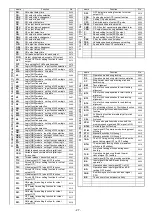
name
Function
No.
D32.
OFF delay time setting function for virtual
output OT3
0519
CPK.
Feed pulse output (CP) cancel function
0520
CP.
Setting CP pulse amount
0521
CPC.
Prohibited angle of output CP pulse
0522
PSW.
Panel switch operation prohibit
0523
CKB.
O4, O5 output cancel during backtack term
0524
CPB.
CP output cancel during backtack term
0525
C.
Speed setting for the [SPC] output
0526
D.
Speed setting for the [SPD] output
0527
E.
Speed setting for the [SPE] output
0528
CNF.
F key function on control panel
0529
PDS.
Variable speed pedal changeover setting
0530
V2C.
Speed instruction VC2 cancellation
0531
name
Function
No.
D1.
Operation mode during tacking
0600
D2.
Operation mode during start tack completion
0601
CT.
Stop time at each corner during start and
backtacking
0602
BM.
Tack alignment
0603
BT1.
No. of stitch compensation for start tacking
alignment
0604
BT2.
No. of stitch compensation for start tacking
alignment
0605
BT3.
No. of stitch compensation for end tacking
alignment
0606
BT4.
No. of stitch compensation for end tacking
alignment
0607
BTP.
No. of tacking stitches (+) 15 stitches function
0608
BTO.
No. of tacking stitches addition stitches
function
0609
BTT.
Full heeling function immediately after start
tacking stop
0610
CSJ.
Not used.
0611
SPN.
The speed operation mode when both the
medium speed signal and S5V signal is ON
0612
BTM.
Set table types of tacking
0613
S7M.
Input signal S7 operation mode during preset
stitching
0614
S7U.
Manual backstitch ON timing 1
0615
S7D.
Manual backstitch ON timing 2
0616
7BD.
The OFF timing setting of output B when the
backstitching signal (S7) is OFF setting.
0617
BTN.
The maximum tacking stitches (maximum
stitches is 99 stitches)
0618
BCC.
No. of end tacking stitches during direct
heeling
0619
TLS.
Operation mode during thread trimmer
cancel signal [TL] setting
0620
BTS.
Input signal BTL quick pressing operation
0621
BS.
Input signal SB and EB quick pressing
operation
0622
BTD.
Operation when input signal BTL is ON
0623
BD.
Operation when input signal SB and EB
tacking OFF are set
0624
PNE.
End tacking cancel mode with input signal
PSU
0625
BZ.
The buzzer of control panel validity
0626
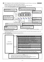
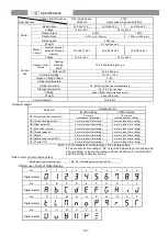
D
m
od
e
(
Fo
r
tacki
ng
set
ti
ng
m
od
e
):
[
↓]
+
[D
]
key
C
m
od
e
(
Fo
r
se
tt
ing
i
np
u
t/
ou
tpu
t
si
gn
al
t
o
f
un
ct
ion
):
[
↓]
+
[C
]
key
C
m
od
e
:
[
↓]
+
[C
]
key


