Mitsubishi Limiservo X G Series Скачать руководство пользователя страница 3


- 2 - 


1. To ensure safe use 

*Always observe the following items to ensure safe use of the industrial sewing machine drive unit (motor and control box).


1.1 Before starting


Read all instruction manuals thoroughly before starting use of this drive unit, and follow the technical manuals. Also read the instruction 

manuals for the installed sewing machine.


1.2 Application and purpose 

This drive unit is designed to drive a sewing machine and must not be used for other applications or purposes. Do not use this drive unit until 

it can be confirmed that safety measures for the installed sewing machine have been taken.


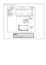
1.3 Work environment 

Use this drive unit in dry and well-kept clean locations, e.g. in the clothing industry, and which process dry sewing material. 
Avoid using this control unit in the following types of environments. 
(1) Power voltage 

- Place where voltage fluctuation exceeds ±10% of the rated voltage. 
- Place where the specified power capacity cannot be secured. (Refer to page 8) 

(2) Electromagnetic 
                          noise 

- Place where strong electric or magnetic fields are generated such as near a large-output high frequency 

oscillator or high frequency welding machine. 

(3) Temperature 
            and humidity 

- Place where atmospheric temperature is 35 degree or higher and 5 degree or lower. 
- Place subject to direct sunlight or outdoors. 
- Near a heat source such as a heater. 
- Place where relative humidity is 45% or less and 85% or more, or where dew condensation occurs. 

(4) Atmosphere 

- Atmosphere with dust or corrosive gases. 
- Atmosphere with combustible gases or explosive atmosphere. 

(5) Altitude 

- Place where altitudes exceeds 1,000m above mean sea level. 

(6) Storage 

- Place where storage temperature is 55 

  or higher and -25

  or lower. 

(7) Vibration 

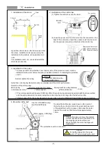
- If excessive vibration occurs when the control box is installed on the sewing machine, install it separately. 
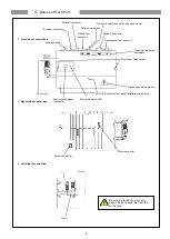
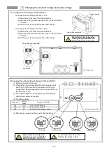
 

2. Installation 

2.1 Motor and control box 

- Correctly install according to the attached technical manuals. 

2.2 Accessories 

- Always disconnect this control unit from the main power supply when installing any accessories listed in the technical manual. (Turn the 

main switch OFF, and remove the plug from the outlet (power supply line).) 
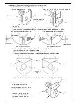
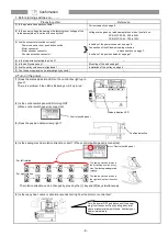
2.3 Cable 

(1) Arrange the connection cable so that excessive force is not applied during use, and do not excessively bend the cable.


(2) Cables near moving parts (e.g., pulley) must be wired at a minimum distance of 25mm. 
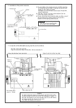
(3) Confirm that the power voltage of the power cable for supplying to the control box meets the specifications on the motor and control box 

rating nameplates before connecting it to the power line. Connect it to the designated places to supply the power. Perform this step with the 
power switch turned OFF. 
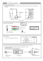
2.4 Grounding 

- Correctly connect the power cable grounding to the power supply grounding. 

2.5 Accompanying appliances and accessories 

- Electric accompanying appliances and accessories must be connected to the place listed in this manual. 

2.6 Removal 

(1) Turn the power switch OFF and remove the plug from the outlet (power supply line) before removing the motor or control box. 
(2) Do not pull on the cord when removing the plug. Always hold the plug itself. 
(3) There is a high voltage applied inside the control box, so always 

wait at least 10 minutes after running the power switch OFF

 and 

remove the plug from the outlet (power supply line) before opening the control box panel. 

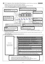
3. Maintenance, inspection and repairs 

- Follow the technical manuals for maintenance and inspection of this control unit. 
- Repairs and maintenance must be done and approved by specially trained personnel. 
- Do not run this control with the ventilation openings of the motor's dust-proof filter blocked or clogged with dust, loose cloth, etc. 
- Always turn the power switch OFF and remove the plug from the outlet (power supply line) before replacing the sewing machine needle or 

bobbin, etc. 

- Always use original replacement parts for repairs or maintenance. 

4. Other safety measures 

- Keep fingers away from all moving machine parts (especially near sewing machine needle, etc.). 
- Do not drop this control unit. 
- Do not operate this product without parts such as the protective cover or protective devices such as the safety breaker. 
- The servomotor surface may reach high temperatures depending on the operation conditions and loads. Do not touch directly. 
- If any damage is observed on this control unit, if the drive does not run properly or if operator is uncertain about operation, do not operate the 

drive unit. Operate the drive only after adjustments, repairs and approvals have been made by qualified personnel. 

- The user must avoid making modifications or changes based on user's judgment. 
- When system have to be stop in case of emergency, remove the power supply plug from the power supply line.   

5. Hazard display, warning display


(1) This symbol indicates risk that may cause personal injury or risk to the machine   

when mishandling of products. 

 
(2) This symbol indicates electrical risks and warnings. 
 
 
(3) This symbol indicates thermal risks and warnings. 

 
- Always deliver this instruction manual to the end user. 
- Save these technical manuals for future reference. 

  2    Safety Instructions


Содержание Limiservo X G Series

Страница 1: ...duction type AC servo motor and control box with automatic needle positioner Thank you for purchasing this product Please read this manual thoroughly before use to ensure safe and proper use Please re...

Страница 2: ...the solenoid voltage and output voltage 12 1 To change solenoid voltage DC24V DC30V 12 2 Changing the output voltage between 0VDC and 5VDC 12 10 Operation of the Control switch Panel Keys 13 1 Display...

Страница 3: ...eets the specifications on the motor and control box rating nameplates before connecting it to the power line Connect it to the designated places to supply the power Perform this step with the power s...

Страница 4: ...The same operation should be taken when the position detector or wires are broken 13 Be sure to ground the lever unit when using it to separate from the control box 14 Always turn off the power switc...

Страница 5: ...achine connector Motor connector Lever Lever Unit Power connector Status indication LED Connector indication nameplate High voltage warning plate XC G10 S control switch panel installation screw hole...

Страница 6: ...djust the belt tension press down on the center of the belt with your hand and turn the upper and lower nuts of the adjustment nut to increase or decrease the center height of the motor so that the be...

Страница 7: ...direction and install between the belt and motor pulley a For counterclockwise rotation b For clockwise rotation Set the center of the protective rod to the position at the center of the belt and mot...

Страница 8: ...Wire the units as shown below Align the connector shape and direction and securely insert it View of control box from cover side View of control box from box side This can not be used with except XC...

Страница 9: ...h insulation tape etc to insulate securely Always ground the green yellow green grounding wire 6 Wire and Grounding Power connector 6 Pole Power connector Power Recommended current capacity Single pha...

Страница 10: ...the sewing machine be rotated lightly by hand 2 Turn on the power 1 Does the status indication LED on the control box light up in green There is a problem if the LED is flickering or is lit up in red...

Страница 11: ...esignated stop position The cross recessed screw A does not need to be loosened at this time Always replace the cover after adjustment 2 Adjustment of pedal toe down pressure and heeling pressure The...

Страница 12: ...Slow start speed S 250 Operation speed Adjust between the low speed L and high speed H using the C and D keys on the control switch panel Caution No matter how large the motor pulley diameter is the...

Страница 13: ...ight Change the output voltage 0 5VDC with the jumper JP5 on the front cover PCB 3 The output voltage can be changed by reconnecting the connector as shown on the right 4 The factory setting Connector...

Страница 14: ...can be investigated Program mode I Save mode of the setting data Program mode R Reset returning to original data The state set with each program mode can be returned to the original settings factory...

Страница 15: ...ay will flicker Press down key press key The program mode C will be entered Switch the function item with the or key Program mode D While holding down the key press the D key for 2 seconds or more fro...

Страница 16: ...er of Function item number selection mode normal mode Press after changing the setting for each function item The display LED will flicker and after the changed items are set the mode will change to t...

Страница 17: ...se when the pedal is pressed down to the fullest The speed ratio is displayed with the two digits LED C and LED D and can be set in the range of 0 to 99 Slow start ON OFF Slow start can be turned ON o...

Страница 18: ...tor and the No of stitches can be set 1 When the except pattern No 4 2 When the pattern No 4 continuous tack stitching Each setting value can be changed from 0 to 9 stitches A B C D E F stitches A mea...

Страница 19: ...pattern 2 or 3 display show 2 or 3 2 Display of continuous tack stitching Pattern 4 3 Display of program stitching Pattern A to H Display of pattern A When pattern B C D E F G or H display show B C D...

Страница 20: ...y setting is 280M B After selecting the function name holds down the D key over 2 seconds or more The function name s set speed and function setting will be set automatically To return to the normal m...

Страница 21: ...700 700 ON OFF H 65 6850 LY3 6850 B1T 2000 250 150 700 700 ON OFF L 410B LU2 4410 B1T 2000 250 175 700 700 ON OFF L 8 412B LU2 4412 B1T 2000 250 175 700 700 ON OFF L 430B LU2 4430 B1T 2000 250 175 700...

Страница 22: ...gs Description A Select the function that corresponds to the sewing machine model for Simple setting table for chain stitch sewing machine on the page 22 After selecting the function name holds down t...

Страница 23: ...tch Electric under thread trimmer 1 6000 200 200 1400 1400 NO7A PEGASUS W T 600 200 series UT device condensed stitch Pneumatic under thread trimmer with pneumatic top cover thread trimmer 1 6000 200...

Страница 24: ...econds or more This completes the settings Description A Select the model name that corresponds to the sewing machine model for the simple setting values for the D RKOPP ADLER thread trimming sewing m...

Страница 25: ...B 6 OB DLU 5490BB 6 WB DLU 5490N 6 DMN 530 5 DMN 531 5 class 2 4200 200 200 1700 1900 JDU JUKI DNU 241H 5 DNU 241H 6 DSC 244 6 DSC 244V 6 DSC 245 5 DSC 245 6 DSC 246 6 DSC 246V 6 DSU 142 6 DSU 144 6 D...

Страница 26: ...sed 0053 D8 Needle DOWN position stop angle 0054 U8 Needle UP position stop angle 0055 name Function No GA Gain high low selection 0100 PDC Pedal curve 0101 AC Acceleration time simple setting 0102 AC...

Страница 27: ...0375 R2R Reset condition of RS F F for I2 0376 R2N RS F F reset stitch amount for I2 0377 name Function No I4 I4 input function selection 0378 I4L I4 input logic changeover 0379 I4A I4 input alternati...

Страница 28: ...or virtual output OT2 0511 T3C Virtual output OT3 forced OFF function 0512 T3T Forced OFF timer setting function for virtual output OT3 0513 D11 ON delay time setting function for virtual output OT1 0...

Страница 29: ...he voltage of VC2 0736 OAD Output signal display 0737 OBD Output signal display 0738 OCD Output signal display 0739 ODD Output signal display 0740 OFD Output signal display 0741 O1D Output signal disp...

Страница 30: ...g 2 O1 OT1 Output 3 VC2 VC2 Variable speed command 4 I5 No setting 5 I1 IO1 Input 6 5V 12V 5V 7 24V 30V 24V 8 I2 U Needle lift signal 9 0V 0V 10 24V 30V 24V 11 O2 NCL Needle cooler output 12 O7 No set...

Страница 31: ...r after turning OFF the power switch 2 Turn ON the power switch and then set the function PDS to ON The lever connector still disconnects 3 Connect the lever connect after turning OFF the power switch...

Страница 32: ...play LED on the control box flickers in orange colored as the interval of 0 3 sec It will be confirmed in error code history after returning to a normal condition M5 An error of the copy mode using th...

Страница 33: ...rating 10 or more continuous time rating OA Thread trimming output T 4 or more short time rating 5 or more short time rating OB Wiper output W 4 or more short time rating 5 or more short time rating O...

Страница 34: ...Reference Dimensions MOTOR and CONTROL BOX Printed in Japan...

Отзывы: