


- 20 -
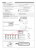
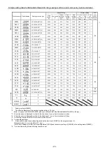
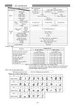
Simple setting table for Mitsubishi thread trimming sewing machine and motor pulley outside diameter.
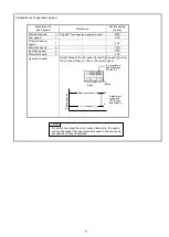
Function name Digital display
Sewing machine type
Speed setting
Function setting
Motor
pulley
outside
diameter
(mm)
High
speed
(H)
Low speed
(L)
Thread
trimming
speed
(T)
Start
tacking
speed
(N)
End
tacking
speed
(V)
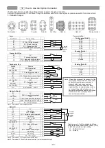
D mode
tack
alignment
(BM)
A mode
weak
brake
(BK)
A mode
gain
selection
(GA)
*3
280M
LS2-1280-M1T (W)
4000
250
200
1700
1700
OFF
OFF
L
*1
280H
LS2-1280-H1T(W)
3000
250
200
1200
1200
OFF
OFF
L
280B
LS2-1280-B1T
3000
250
200
1200
1200
OFF
OFF
L
380M
LS2-1380-M1T(W)
4000
250
200
1700
1700
OFF
OFF
L
380H
LS2-1380-H1T(W)
3000
250
200
1200
1200
OFF
OFF
L
380B
LS2-1380-B1T
3000
250
200
1200
1200
OFF
OFF
L
85
210M
LS2-2210-M1T(W)
4000
250
200
1700
1700
OFF
OFF
L
230M
LT2-2230-M1TW
3700
250
175
1200
1200
OFF
OFF
H
230B
LT2-2230-B1T
3000
250
175
1200
1200
OFF
OFF
H
250M
LT2-2250-M1TW
3000
250
175
1200
1200
OFF
OFF
H
250B
LT2-2250-B1T
3000
250
175
1200
1200
OFF
OFF
H
3310
LY2-3310-B1T
2000
250
225
700
700
ON
OFF
H
3319
LY2-3319-B1T
2000
250
225
700
700
ON
OFF
H
*2
3750
LY2-3750-B1T
2000
250
200
700
700
ON
OFF
L
6840
LY3-6840-B0T
2000
250
150
700
700
ON
OFF
H
65
6850
LY3-6850-B1T
2000
250
150
700
700
ON
OFF
L
410B
LU2-4410-B1T
2000
250
175
700
700
ON
OFF
L
*8
412B
LU2-4412-B1T
2000
250
175
700
700
ON
OFF
L
430B
LU2-4430-B1T
2000
250
175
700
700
ON
OFF
L
4650
LU2-4650-B1T
3000
250
175
700
700
ON
OFF
L
*8
4652
LU2-4652-B1T
3000
250
175
700
700
ON
OFF
L
85
4710
LU2-4710-B1T
3000
250
175
700
700
ON
OFF
L
4730
LU2-4730-B1T
2500
250
175
700
700
ON
OFF
L
630
LX2-630-M1
800
280
160
500
500
ON
ON
L
65
280E
LS2-1280-M1T(W)
5000
250
200
1700
1700
OFF
OFF
H
110
FL
*5
5000
250
200
1700
1700
OFF
OFF
L
N
*6
5000
250
200
1700
1700
OFF
OFF
L
LOAD2
*7
*4
LOAD1
*7
*1 Factory setting is [280M].
*2 The effective diameter of the sewing machine pulley is 70 mm.
(Note : In case of LY2-3310/3319/3750 is 80 mm, LU2-4410/4412/4430/4650/4652/4710/4730 is 85 mm.)
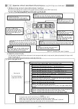
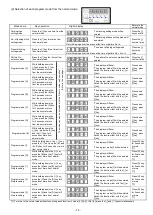
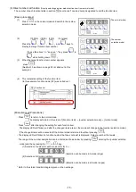
*3 A function name is displayed in order to the direction of
↓ every time it presses a [↓] key.
*4 A function name is displayed in order to the direction of
↑ every time it presses a [↑] key.
*5 For sewing machine with foot lifter, without thread trimmer.
*6 For needle positioner.
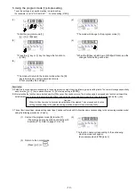
*7 It is possible to load the saved setting data by the function of [SAVE*] in the program mode [ I ].
( Program mode [ I ] : [
↓]
+
[
↑]
+
[B]
+
[C] key )
( The factory setting of [LOAD1] is the setting data of [412B] and the factory setting of [LOAD2] is the setting data of [280M]. )
*8 The short remaining thread trimming function is set.


