Mitsubishi Limiservo X G Series Скачать руководство пользователя страница 26


- 25 - 


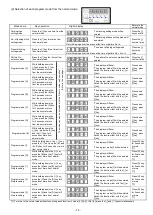
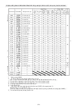
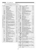
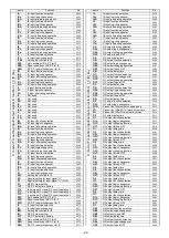
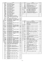
Refer to the Technical Documents for details on each function.


The numbers in the table are used with the direct number call function.


name


Function


No.


H. 

Maximum speed


0000


L. 

Low speed


0001 


T. 

Thread trimming speed


0002 


N. 

Start tacking speed


0003 


V. 

End tacking speed


0004 


M. 

Medium speed


0005 


S. 

Slow start speed


0006 


SLN. 

No. of slow start stitches


0007 


SLM. 

Slow start operation mode


0008 


SLP. 

Slow start when power is turned ON


0009 


SH. 

One shot


0010 


SHM. 

One shot operation mode


0011 


PSU. 

No. of stitches after PSU input


0012 


PSD. 

No. of stitches after PSD input


0013 


PS1. 

Sensor input signal PS1 operation mode


0014 


1. 

No. of stitches after PS1 input


0015 


PS2. 

Sensor input signal PS2 operation mode


0016 


2. 

No. of stitches after PS2 input


0017 


PSN. 

Restart after PSD,SEN input PSN


0018 


SEN. 

Input sensor function valid / invalid


0019 


SE. 

Setting stitch amount to stop by "SEN"


0020 


FUM. 

Presser foot lift momentary


0021 


FU. 

FUM operation mode


0022 


FCT. 

Time setting for FUM operation mode


0023 


FD. 

Time to motor drive after presser foot lifter 
bring down


0024 


FO. 

Full wave time of presser foot lifter output


0025 


S3D. 

Delay time of presser foot signal S3 input


0026 


FUD. 

Presser foot lifting output chopping duty


0027 


PFU. 

Presser  foot  lifting  output  when  power  is 
turned ON


0028 


FL. 

Cancel the presser foot lifting with full heeling


0029 


S3L. 

Cancel presser foot lifting with light heeling


0030 


S2L. 

Cancel of thread trimming operation


0031 


S6L. 

Thread trimming protection signal (S6) logical 
changeover


0032 


AT. 

Automatic operation


0033 


TL. 

Thread trimmer cancel


0034 


TLS. 

Auto-stop of preset stitch sewing before trim


0035 


RU. 

Reverse run needle lifting after thread 
trimming


0036 


R8. 

RU reverse run angle


0037 


TB. 

Thread trimming with reverse feed


0038 


TBJ. 

Not used.


0039 


S2R. 

Full heeling, S2 signal operation mode


0040 


IL. 

Cancel of interlock after full pedal heeling


0041 


TR. 

Thread trimming mode


0042 


POS. 

Thread trimming validity at neutral pedal


0043 


P1P. 

Operation when power is turned ON during 1 
position setting.


0044 


P2P. 

Operation when power is turned ON during 2 
position setting.


0045 


C8. 

Needle stop position before fabric


0046 


K8. 

Reverse run angle from DOWN position to 
UP position


0047 


E8. 

On angle of virtual "TM"


0048 


S8. 

On start angle of virtual "TM"


0049 


SNM. 

Setting sensor "SEN" input function


0050 


KD. 

Virtual down setting


0051 


KDU. 

Virtual width of up and down signal


0052 


PSJ. 

Not used.


0053 


D8. 

Needle DOWN position stop angle


0054 


U8. 

Needle UP position stop angle


0055 


name


Function


No.


GA. 

Gain high/low selection


0100 


PDC. 

Pedal curve


0101 


AC. 

Acceleration time simple setting


0102 


ACT. 

Acceleration time


0103 


DC. 

Deceleration time simple setting


0104 


DCT. 

Deceleration time


0105 


SC. 

S-character cushion


0106 


SCT. 

S-character cushion time setting


0107 


S2M. 

Full heeling S2 signal operation mode when 
power is turned on or after thread trimming


0108 


PL. 

Sewing machine shaft/motor shaft speed 
setting selection 

0109 


MR. 

Setting motor pulley diameter 

0110 


SR. 

Setting sewing machine pulley diameter 

0111 


NOS. 

Random stop is available without thread 
trimming.


0112 


STM. 

First priority stop => speed control 

0114 


BKT. 

Brake time


0115 


B8. 

Weak brake angle


0116 


BNR. 

Reduction of weak brake sound


0117 


BKS. 

Weak brake force


0118 


BKM. 

Weak brake mode


0119 


BK. 

Weak brake


0120 


S. 

Display sewing speed


0200 


N. 

Down counter setting count amount


0201 


D. 

Down counter display count amount


0202 


P. 

Up counter setting count amount


0203 


U. 

Up counter display count amount


0204 


CUP. 

Up counter the selection of setting mode


0205 


USC. 

Up counter the selection of counter operation


0206 


UCM. 

Up counter changing sewing pattern


0207 


UPC. 

Up counter valid / invalid


0208 


NXU. 

Up counter operation after counting over


0209 


CDN. 

Down counter the selection of setting mode


0210 


DSC. 

Down counter the selection of counter 
operation


0211 


DCM. 

Down counter changing sewing pattern


0212 


DNC. 

Down counter valid / invalid


0213 


NXD. 

Down counter operation after counting over


0214 


PCM. 

Counter condition turning on power switch


0215 


PRN. 

Setting Thread trimming times "N"


0216 


CNU. 

Setting Number of stitches "N"


0217 


CCI. 

Count modification (to use IO1, IO2)


0218 


PMD. 

Display condition turning on power switch


0219 


CCM. 

Reset for Up / Down counter during operation 

0220 

Program mode [I] (Save mode of the setting data ): [

↓]+[↑]+[B]+[C] key


name


Function


No.


SAVE1 

Save mode of the setting data 1


SAVE2 

Save mode of the setting data 2


CCR 

Copy of the current data 


CU1 

Copy of user

’s 1 data   


CU2 

Copy of user

’s 2 data 

Program mode [R] (Reset): [

↓]+[B]+[C] key


name


Function


No.


RESET. 

Reset


Program mode [1] (Mitsubishi sewing machine): [

↓]+[A]+[B] key


name


Function


No.


280M 

LS2-1280-M1T(W)


    : 

    :


LOD1 

Load of the saved setting data1 

Program mode [2] (Chain stitch sewing machine): [

↓]+[C]+[D]


key


name


Function


No.


YU2 

YAMATO VC2600,VC2700 class


    : 

    :


JMH 

JUKI 

Program mode [3] (other lock stitch sewing machine): [

↓]+[A]+[D] key 


name


Function


No.


D697 

DÜRKOPP ADLER 697-15000 class


    : 

    :


750 

SINGER 


  11    Function List


P

 m

od

(Fo

sew

ing

 m

ac

hi

ne

):

 [

↓]

+[

 ↑

ke

y


A

 m

od

e

 (

Fo

se

rvo

 m

o

tor

[↓

]+[

A

ke

y


B

 m

od

e

 (

For

 c

o

u

n

te

r/

s

p

e

e

d

 d

is

p

lay

)

 :

 [

↓]

+

[B

key


Содержание Limiservo X G Series

Страница 1: ...duction type AC servo motor and control box with automatic needle positioner Thank you for purchasing this product Please read this manual thoroughly before use to ensure safe and proper use Please re...

Страница 2: ...the solenoid voltage and output voltage 12 1 To change solenoid voltage DC24V DC30V 12 2 Changing the output voltage between 0VDC and 5VDC 12 10 Operation of the Control switch Panel Keys 13 1 Display...

Страница 3: ...eets the specifications on the motor and control box rating nameplates before connecting it to the power line Connect it to the designated places to supply the power Perform this step with the power s...

Страница 4: ...The same operation should be taken when the position detector or wires are broken 13 Be sure to ground the lever unit when using it to separate from the control box 14 Always turn off the power switc...

Страница 5: ...achine connector Motor connector Lever Lever Unit Power connector Status indication LED Connector indication nameplate High voltage warning plate XC G10 S control switch panel installation screw hole...

Страница 6: ...djust the belt tension press down on the center of the belt with your hand and turn the upper and lower nuts of the adjustment nut to increase or decrease the center height of the motor so that the be...

Страница 7: ...direction and install between the belt and motor pulley a For counterclockwise rotation b For clockwise rotation Set the center of the protective rod to the position at the center of the belt and mot...

Страница 8: ...Wire the units as shown below Align the connector shape and direction and securely insert it View of control box from cover side View of control box from box side This can not be used with except XC...

Страница 9: ...h insulation tape etc to insulate securely Always ground the green yellow green grounding wire 6 Wire and Grounding Power connector 6 Pole Power connector Power Recommended current capacity Single pha...

Страница 10: ...the sewing machine be rotated lightly by hand 2 Turn on the power 1 Does the status indication LED on the control box light up in green There is a problem if the LED is flickering or is lit up in red...

Страница 11: ...esignated stop position The cross recessed screw A does not need to be loosened at this time Always replace the cover after adjustment 2 Adjustment of pedal toe down pressure and heeling pressure The...

Страница 12: ...Slow start speed S 250 Operation speed Adjust between the low speed L and high speed H using the C and D keys on the control switch panel Caution No matter how large the motor pulley diameter is the...

Страница 13: ...ight Change the output voltage 0 5VDC with the jumper JP5 on the front cover PCB 3 The output voltage can be changed by reconnecting the connector as shown on the right 4 The factory setting Connector...

Страница 14: ...can be investigated Program mode I Save mode of the setting data Program mode R Reset returning to original data The state set with each program mode can be returned to the original settings factory...

Страница 15: ...ay will flicker Press down key press key The program mode C will be entered Switch the function item with the or key Program mode D While holding down the key press the D key for 2 seconds or more fro...

Страница 16: ...er of Function item number selection mode normal mode Press after changing the setting for each function item The display LED will flicker and after the changed items are set the mode will change to t...

Страница 17: ...se when the pedal is pressed down to the fullest The speed ratio is displayed with the two digits LED C and LED D and can be set in the range of 0 to 99 Slow start ON OFF Slow start can be turned ON o...

Страница 18: ...tor and the No of stitches can be set 1 When the except pattern No 4 2 When the pattern No 4 continuous tack stitching Each setting value can be changed from 0 to 9 stitches A B C D E F stitches A mea...

Страница 19: ...pattern 2 or 3 display show 2 or 3 2 Display of continuous tack stitching Pattern 4 3 Display of program stitching Pattern A to H Display of pattern A When pattern B C D E F G or H display show B C D...

Страница 20: ...y setting is 280M B After selecting the function name holds down the D key over 2 seconds or more The function name s set speed and function setting will be set automatically To return to the normal m...

Страница 21: ...700 700 ON OFF H 65 6850 LY3 6850 B1T 2000 250 150 700 700 ON OFF L 410B LU2 4410 B1T 2000 250 175 700 700 ON OFF L 8 412B LU2 4412 B1T 2000 250 175 700 700 ON OFF L 430B LU2 4430 B1T 2000 250 175 700...

Страница 22: ...gs Description A Select the function that corresponds to the sewing machine model for Simple setting table for chain stitch sewing machine on the page 22 After selecting the function name holds down t...

Страница 23: ...tch Electric under thread trimmer 1 6000 200 200 1400 1400 NO7A PEGASUS W T 600 200 series UT device condensed stitch Pneumatic under thread trimmer with pneumatic top cover thread trimmer 1 6000 200...

Страница 24: ...econds or more This completes the settings Description A Select the model name that corresponds to the sewing machine model for the simple setting values for the D RKOPP ADLER thread trimming sewing m...

Страница 25: ...B 6 OB DLU 5490BB 6 WB DLU 5490N 6 DMN 530 5 DMN 531 5 class 2 4200 200 200 1700 1900 JDU JUKI DNU 241H 5 DNU 241H 6 DSC 244 6 DSC 244V 6 DSC 245 5 DSC 245 6 DSC 246 6 DSC 246V 6 DSU 142 6 DSU 144 6 D...

Страница 26: ...sed 0053 D8 Needle DOWN position stop angle 0054 U8 Needle UP position stop angle 0055 name Function No GA Gain high low selection 0100 PDC Pedal curve 0101 AC Acceleration time simple setting 0102 AC...

Страница 27: ...0375 R2R Reset condition of RS F F for I2 0376 R2N RS F F reset stitch amount for I2 0377 name Function No I4 I4 input function selection 0378 I4L I4 input logic changeover 0379 I4A I4 input alternati...

Страница 28: ...or virtual output OT2 0511 T3C Virtual output OT3 forced OFF function 0512 T3T Forced OFF timer setting function for virtual output OT3 0513 D11 ON delay time setting function for virtual output OT1 0...

Страница 29: ...he voltage of VC2 0736 OAD Output signal display 0737 OBD Output signal display 0738 OCD Output signal display 0739 ODD Output signal display 0740 OFD Output signal display 0741 O1D Output signal disp...

Страница 30: ...g 2 O1 OT1 Output 3 VC2 VC2 Variable speed command 4 I5 No setting 5 I1 IO1 Input 6 5V 12V 5V 7 24V 30V 24V 8 I2 U Needle lift signal 9 0V 0V 10 24V 30V 24V 11 O2 NCL Needle cooler output 12 O7 No set...

Страница 31: ...r after turning OFF the power switch 2 Turn ON the power switch and then set the function PDS to ON The lever connector still disconnects 3 Connect the lever connect after turning OFF the power switch...

Страница 32: ...play LED on the control box flickers in orange colored as the interval of 0 3 sec It will be confirmed in error code history after returning to a normal condition M5 An error of the copy mode using th...

Страница 33: ...rating 10 or more continuous time rating OA Thread trimming output T 4 or more short time rating 5 or more short time rating OB Wiper output W 4 or more short time rating 5 or more short time rating O...

Страница 34: ...Reference Dimensions MOTOR and CONTROL BOX Printed in Japan...

Отзывы: